5
2 INSTALLATION…
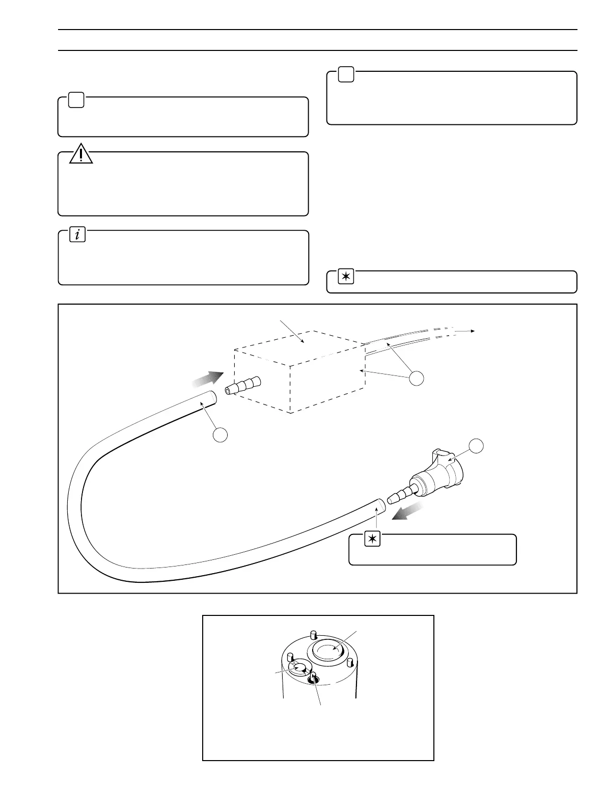
Fig. 2.5 Location of Water Wash Nozzle
Sensor
Water Wash
Nozzle
Liquid
Junction
Note. It is advisable to use a
suitable hose clamp.
Fig. 2.4 Installing the Water Wash Water Supply
Install a suitable solenoid valve to
the mains water supply feed.
Connect a suitable length of
1
/4
in. i.d. p.v.c. tube to the outlet of the
solenoid valve. This tube terminates at the electrode installation point.
Push the quick-fit
connector supplied, onto
the free end of the tube.
Note that the quick-fit
connector incorporates a
cut-off valve.
To water supply – see
Important Note and
Caution, above.
Suitable Solenoid Valve (user supplied)
2
1
3
2.2 Water Supply for Water Wash Systems –
Fig. 2.4 and 2.5
✶
Important Note. Installation must only be carried
out in accordance with the local water authority and
council bylaws.
Caution. The maximum water pressure at the
electrode should not exceed 4 bar. At NO time should the
sample pressure be allowed to exceed that of the water
wash water supply. Fit a non return valve if this possibility
exists.
Information. As all quick-fit connectors used in
Water Wash systems incorporate cutoff valves, tubes
may subsequently be disconnected on operational
equipment without sample loss or water wash discharge.
✶
Note. For optimum performance of the Water Wash
function in flow systems, the sample pressure should be
at least 2 bars lower than that of the water wash water
supply.
The water supply for the water wash system must come from a
suitable supply via a solenoid valve. The general specification
for the solenoid valve is:
Brass body: 2/2, NC
Orifice size: 3.0 / 4.0 mm
Port size:
1
/8" –
1
/4" BSP
Pressure: 0 to 6 bar
Coil: 110/115 V a.c. or 230/240 V a.c. 50/60 Hz
Before fitting the electrode cartridge system, install the water
supply as shown in Fig. 2.3.
Note. See Fig. 2.4 for recommended tubing.