4
2 INSTALLATION
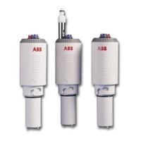
2.1 Typical Installation
A typical installation is shown in Fig. 2.1, with offset ported
flowcell arrangements illustrated in Fig. 2.3. A recommended
installation for samples which may have entrained air or are
subject to intermittent flow is shown in Fig. 2.2.
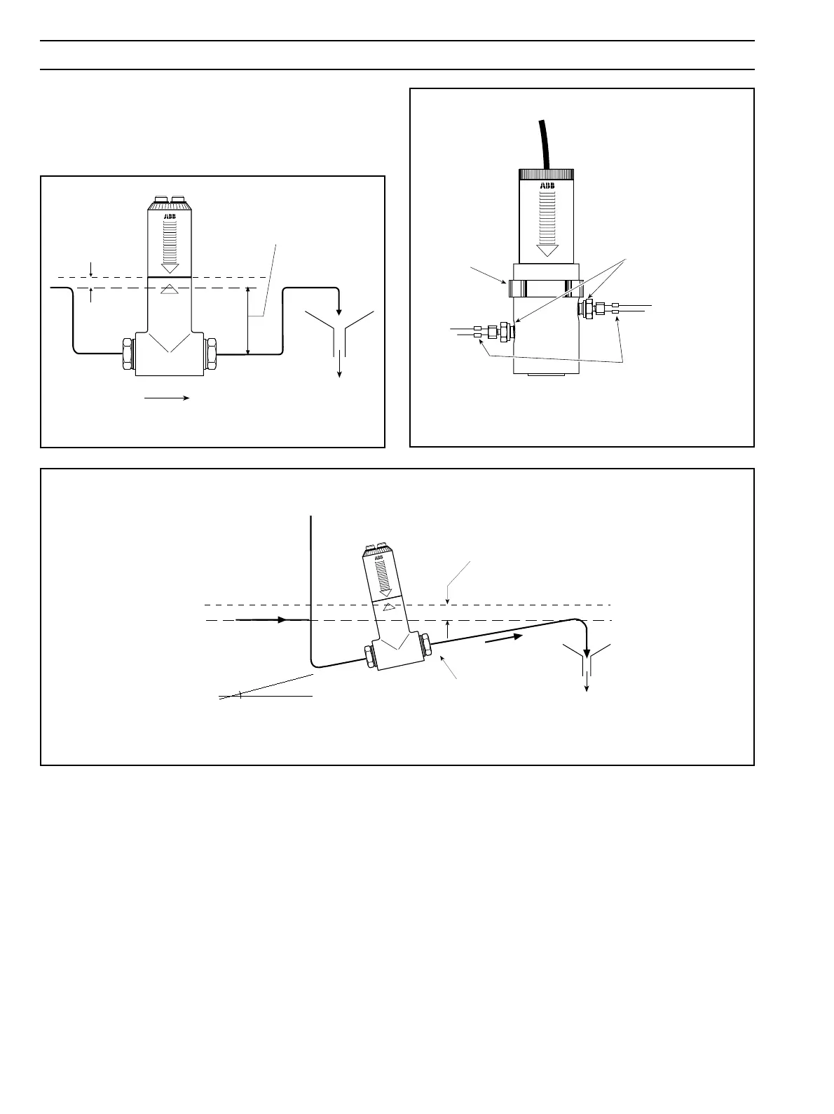
Fig. 2.3 Installation of Offset Ported Flowcell Assembly
IN
OUT
3
/
8
in NPT
Male Stud Couplings
(not supplied)
Clamp (Optional)
Recommended clamps
(not supplied)
Fig. 2.1 Typical Installation
To ensure that the cartridge
is always in solution.
To prevent spillage
when cartridge is
removed.
Sample Flow
Drain
Fig. 2.2 Recommended Installation for Samples with Entrained Air or Intermittent Flow
To prevent spillage when
cartridge is removed.
B
Approximately 15°
Vent
A
Point B must be lower than point A
to ensure that the cartridge is always
in solution.
Drain