ABB Limited
Measurement & Analytics
Howard Road, St. Neots
Cambridgeshire, PE19 8EU
UK
Tel: +44 (0)1480 475 321
Fax: +44 (0)1480 217 948
Email: instrumentation@gb.abb.com
45 x 45mm
off all power. Remove instrument by gripping the sides of the
front panel and pulling the instrument out of its housing. Note its orientation.
Panel-Mounting
The mounting panel must be rigid and may be up to 6.0mm
(0.25 inches) thick. The cut-out required for the instrument is
shown on the right. Instruments may be mounted side-by-side
in a multiple installation for which the cut-out width (for n
instruments) is (48n-4)mm or (1.89n-0.16)inches.
Rear Terminal Wiring
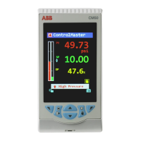
Note: At first power-up the message
is displayed, as
described in section 8 of this manual. Access to other menus is denied
until configuration mode is completed
Select mode is used to access the configuration and operation menu functions.
It can be accessed at any time by holding down and pressing .
Once in select mode, press or to select the required mode. An unlock code is
required to prevent unauthorised entry to Configuration, Setup & Automatic Tuning modes.
Press or to enter the correct code number, then press to proceed.
Mode Upper
Display
Lower
Display
Description Default Unlock
Codes
Normal instrument operation. None
Set Up
Tailor settings to the application.
Configures the instrument for use.
Check manufacturing information. None
Auto-Tuning
Invoke Pre-Tune or Self-Tune.
Note: The instrument will always return automatically to Operator mode if there is no
key activity for 2 minutes.
First select Configuration mode from Select mode (refer to section 2).
Press to scroll through the parameters, then press or to set the required value.
To accept a change must be pressed, otherwise parameter will revert to previous value.
To exit from Configuration mode, hold down and press , to return to Select mode.
Note: Parameters displayed depends on how instrument has been configured.
Parameters marked * are repeated in Setup Mode.
Parameter Lower
See following table for possible codes J T/C
Scale Range Lower Limit +100 to Range Max
Range Min. to Scale Range Upper Limit -100 Range min
0=XXXX, 1=XXX.X, 2=XX.XX, 3=X.XXX
Control Type
Primary & Secondary (heat/cool)
Reverse Acting Primary Output
Control Action
Direct Acting
Band Alarm
Alarm 1Type
No alarm
Range Min. to Range Max
in display units
Range Min.
1 LSD to span from setpoint in display units
+/- Span from setpoint in display units
1 LSD to full span in display units
Band Alarm
Alarm 2 Type
No alarm
Range Min. to Range Max
in display units
Range Min.
1 LSD to span from setpoint in display units
+/- Span from setpoint in display units
1 LSD to full span in display units
Loop Alarm
(disabled) or
(enabled)
Loop Alarm Time*
1 sec to 99 mins. 59secs
(only applies if primary proportional band = 0)
Alarm 2 inhibited
Alarm Inhibit
Alarm 1 and alarm 2 inhibited
Logical Alarm 1 OR 2, Direct
Logical Alarm 1 OR 2, Reverse
Logical Alarm 1 AND 2, Direct
Output 1 Usage
Logical Alarm 1 AND 2, Reverse
Logical Alarm 1 OR 2, Direct
Logical Alarm 1 OR 2, Reverse
Logical Alarm 1 AND 2, Direct
Output 2 Usage
Logical Alarm 1 AND 2, Reverse
Input Ranges and Types
(See Configuration Mode Parameter
)
Code Input Type & R ange Code Input Type & Range Code Input Type & R ange
bC
bCbC
bC
B: 100 – 1824 ºC
L
LL
L.C
CC
C
L: 0.0 – 537.7 ºC
bF
bFbF
bF
B: 211 – 3315 ºF
L
LL
L.F
FF
F
L: 32.0 – 999.9 ºF
P24F
P24FP24F
P24F
PtRh20% vs 40%:
32 – 3362 ºF
CC
CCCC
CC
C: 0 – 2320 ºC
NC
NCNC
NC
N: 0 – 1399 ºC
PTC
PTCPTC
PTC
Pt100: -199 – 800 ºC
CF
CFCF
CF
C: 32 – 4208 ºF
NF
NFNF
NF
N: 32 – 2551 ºF
PtF
PtFPtF
PtF
Pt100: -328 – 1472 ºF
JC
JCJC
JC
J: -200 – 1200 ºC
rC
rCrC
rC
R: 0 – 1759 ºC
Pt
PtPt
Pt.C
CC
C
Pt100: -128.8 – 537.7 ºC
JF
JFJF
JF
J: -328 – 2192 ºF
rF
rFrF
rF
R: 32 – 3198 ºF
Pt
PtPt
Pt.F
FF
F
Pt100: -199.9 – 999.9 ºF
j
jj
j.C
CC
C
J: -128.8 – 537.7 ºC
SC
SCSC
SC
S: 0 – 1762 ºC
0 – 20 mA DC
j
jj
j.F
FF
F
J: -199.9 – 999.9 ºF
SF
SFSF
SF
S: 32 – 3204 ºF
4 – 20 mA DC
KC
KCKC
KC
K: -240 – 1373 ºC
tC
tCtC
tC
T: -240 – 400 ºC
0 – 50 mV DC
KF
KFKF
KF
K: -400 – 2503 ºF
tF
tFtF
tF
T: -400 – 752 ºF
10 – 50 mV DC
k
kk
k.C
CC
C
K: -128.8 – 537.7 ºC
t.C
t.Ct.C
t.C
T: -128.8 – 400.0 ºC
0 – 5 V DC
K
KK
K.F
FF
F
K: -199.9 – 999.9 ºF
t.F
t.Ft.F
t.F
T: -199.9 – 752.0 ºF
1 – 5 V DC
LC
LCLC
LC
L: 0 – 762 ºC
0 – 10 V DC
LF
LFLF
LF
L: 32 – 1403 ºF
P24C
P24CP24C
P24C
PtRh20% vs 40%:
0 – 1850 ºC
2 – 10 V DC
el gasket; it is a seal against dust and
Installation and configuration should be performed only by
personnel who are technically competent to do so. Local Regulations regarding
electrical installation & safety must be observed.
CONCISE PRODUCT MANUAL – IM/C50
Hold instrument firmly in position
(apply pressure to bezel only)
Slide mounting clamp over the
instrument housing towar ds rear face
of mounting panel until the tongues
engage in ratchets and instrument is
CAUTION: Check information label on
housing for correct operating voltage
before c onnecting supply to Power Input
Fuse: 100 – 240V ac – 1amp anti-surge
Option 2 is only available on
model C50K-2110-00.
USE COPPER CONDUCTORS
(EXCEPT FOR T/C INPUT)
Single Strand wire gauge: