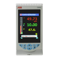
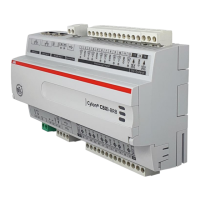
Do you have a question about the ABB C100 and is the answer not in the manual?
Recommends an RS422/485 communications driver with galvanic isolation for the host computer.
Explains configuring MODBUS serial communications as either two-wire or four-wire links.
Shows diagrams for two-wire operation for panel and wall/pipe mounted instruments.
Shows diagrams for four-wire operation for panel and wall/pipe mounted instruments.
Explains the need for pull-up/pull-down resistors to prevent false triggering of slaves.
Details the requirement of a 120Ω termination resistor for long transmission lines.
Provides information on slave limits for RS422/RS485 and cable types for different lengths.
Describes how to access the Configuration Mode using a security switch.
Explains setting baud rate and parity for serial communication.
Details assigning a unique MODBUS address (1-99) to each slave.
Explains the master/slave principle, broadcast address, and slave response timing.
Lists and describes MODBUS function codes like Read Coil Status, Read Holding Register, etc.
Explains how to query ON/OFF status of logic coils and the response format.
Details the message structure for reading coil status, including offset and quantity.
Describes the format of the response data for coil status queries.
Explains how to query holding registers and the response format for data.
Details the message structure for reading holding registers, including offset and quantity.
Describes the format of the response data for holding register queries.
Explains how to force a single coil ON or OFF and its response.
Details the message structure for forcing a single coil's state.
Describes the confirmation response after altering a coil's state.
Explains how to modify the contents of a holding register.
Details the message structure for writing a value to a single register.
Describes the response confirming a register value has been altered.
Explains how to test the MODBUS system using a loopback test.
Details the message structure for initiating a loopback test.
Describes the response received after a loopback test.
Explains how to change the contents of up to eight holding registers simultaneously.
Details the message structure for writing multiple register values.
Describes the response confirming multiple registers have been updated.
Lists and defines MODBUS exception response codes sent by the slave.
Provides examples of exception responses for illegal function or data address.
Lists addressable coils for COMMANDER 100/V100, including variable label and read/write status.
Lists addressable registers for COMMANDER 100/V100, including Analog Inputs.
Continues listing addressable registers for COMMANDER 100/V100, covering Control Settings.
Details registers for Control Settings on COMMANDER 100/V100.
Continues listing addressable registers for COMMANDER 100/V100, covering Set Points, Alarm Settings, and Ramp/Soak Settings.
Lists registers for Set Points on COMMANDER 100/V100.
Lists registers for Alarm Settings on COMMANDER 100/V100.
Lists registers for Ramp/Soak Settings on COMMANDER 100/V100.
Lists addressable coils for COMMANDER 150/160, including variable label and read/write status.
Lists addressable registers for COMMANDER 150/160, including Analog Inputs and Alarm Settings.
Continues listing addressable registers for COMMANDER 150/160, covering Totalizer Settings and Maths Functions.
Lists registers for Totalizer Settings on COMMANDER 150/160.
Lists registers for Maths Functions on COMMANDER 150/160.
| Input Voltage | 24 V DC |
|---|---|
| Storage | 128 MB Flash |
| Resolution | 128 x 64 pixels |
| Output Voltage | 24 V DC |
| Protection Class | IP20 |
| Weight | 0.5 kg |
| Type | Controller |
| Number of Outputs | 8 |
| Communication Ports | RS-232, RS-485 |
| Programming Language | Ladder Logic, Function Block Diagram, Structured Text |
| CPU | 32-bit |
| Operating System | Real-time operating system (RTOS) |
| Memory | 64 MB RAM |
| Display | LCD |
| Output Current | 0.5 A per channel |


