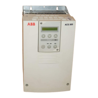
Do you have a question about the ABB COMMANDER 300 and is the answer not in the manual?
Explains the meaning of Warning, Caution, and Note symbols used in the instructions for safety and clarity.
Lists factory-programmed serial data settings such as Instrument Identity, Parity, Block Check Character, and Transmission Rate.
Details recommended OPTO22 boards for PC connection and required jumper configurations for C300 serial instruments.
Describes the physical wiring for serial connections, including parallel setup, RS485/RS422 standards, and cable selection criteria for varying distances.
Details the selection of termination resistor links using plug-in links on the controller, referencing Fig. 5.1 for proper configuration.
Specifies the ANSI-X3.28 based protocol used for master (host) to slave (C300 Controller) communication systems, including the transmission structure.
Explains the configuration of the Serial Data Communication Page, covering Transmission Rate, Controller Identification, Parity, and Block Check Character options.
Explains the coded commands (R, M, W) used for communication and introduces mnemonics and relay logic equations for controller parameters.
Defines the components of a command message, such as STX, Command, Instrument Identification, Parameter Mnemonic, Data, Limiter (ETX), and BCC.
Details the structure of controller replies, explaining the meaning of Instrument Identification, Data, Error Code, Reply codes (ACK, NAK, ETB), and Block Check Character.
Provides practical examples of sending commands (Read, Multiple Read) and receiving replies, including scenarios for understood commands and error notifications with specific error codes.
Provides a comprehensive list of error codes from 01 to 28, detailing the specific error condition associated with each code for troubleshooting serial communication problems.
Lists various general parameters like Measured Variable, Set Point, Control Output, Self-Tune Type, and PID terms, along with their corresponding mnemonics and communication capabilities.
Details control page parameters like Time Units, Cycle Time, and Set Point parameters such as Local/Remote Set Point Adjust Enable and Limits, with their communication mnemonics.
Lists parameters for Input Type, Lineariser Type, Remote Set Point configurations, and Position Feedback settings, detailing their mnemonics and read/write access.
Covers parameters for display scaling, units, analogue output, and configuring alarm types, trip levels, and relay actions with their respective mnemonics.
Lists parameters for Process Alarms hysteresis, status, acknowledged state, alarm acknowledge enable, and relay states and logic equations, including syntax checks.
Covers setup parameters for control functions like power failure modes, logic inputs, and position feedback settings like Ratio Value, Bias Value, and Deadband Value.
Lists parameters for managing program profiles, such as Profile Status, Countdown Time, Current Programme, Segment Time, Time Delay, Profile Start, and Hold State.
Lists control page parameters for Heat/Cool modes, such as Cycle Time, Proportional Band, Integral Action Time, Manual Reset, and output limits for heat and cool.
Defines parameter groups for 'Multiple Read' commands, including General, Control, Process Variable Input, Remote Set Point Input, Position Feedback, Alarm Status, and Alarm Parameters.
Lists remaining parameter groups for 'Multiple Read' commands, including Self-tune, Display, Local Set Point, Dual Set Point, Remote Set Point, and Set Up Control Parameters.
Provides instructions for initial setup and testing of serial communication, including checking controller functionality, connections, and parameter compatibility before troubleshooting.
Outlines the technical specifications for serial communication, including supported EIA standards (RS422/RS485), parity, block check character, and transmission line length.
Lists control characters and printable characters, showing their ASCII representation, decimal value, and hexadecimal code for serial communication reference.
Explains the caution regarding write cycle limits on non-volatile memory registers and how the Non-volatile Save State parameter affects data retention on power loss.
Details the method for calculating the BCC based on the binary sum of message characters and provides a step-by-step example of the calculation.
| Model | COMMANDER 300 |
|---|---|
| Type | Controller |
| Input Voltage | 100-240 VAC |
| Display | LCD |
| Protection Class | IP20 |
| Communication Protocols | Modbus RTU |
| Inputs | Digital, Analog |
| Outputs | Relay, Analog |


