4
6 PROTOCOL
The protocol used is based on ANSI-X3.28-
1976-2.5-A4 and is used for master (host
computer) to slave (C300 Controller)
systems. This is the recommended protocol
for use with supervisory systems such as ABB
Kent-Taylor PC30. The Protocol is:
Start transmission (STX) – Command –
Identification … End transmission (ETX)
– see Figs. 8.1 to 8.6 on pages 7 and 8.
Transmission of commands and processing
of the subsequent replies must be
incorporated into the host computer
programme.
5 SETTING UP
For all aspects other than serial data
transmission the controller is set up as
shown in the Operating Instructions (IM/
C300). Unless otherwise requested, the
instrument is despatched with a
transmission rate of 9600 baud and
transmission line termination resistors
linked-out. If the resistors are to be linked-in
(see Fig. 4.2) carry out the following section.
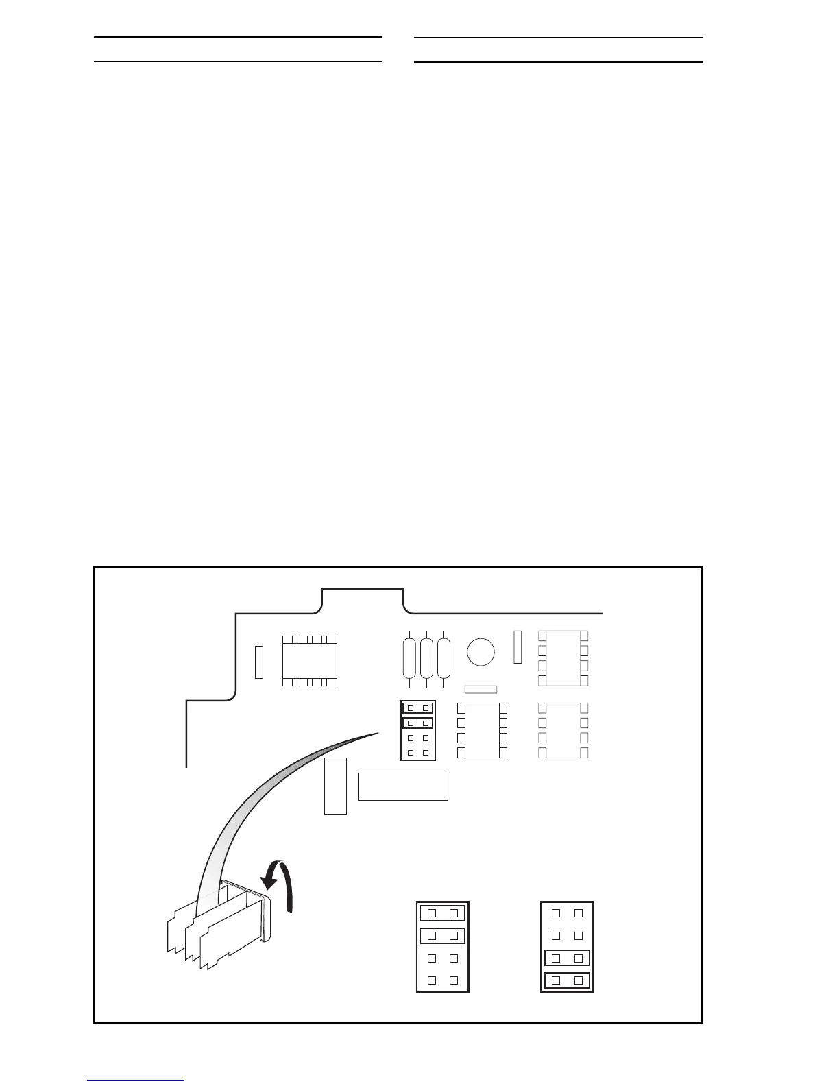
5.1 Termination
Resistors – Fig. 5.1
For long transmission lines, termination
resistors are required on the last C300
Controller in the chain and at the host
computer/computer terminal – see Fig. 4.2.
Under normal operating conditions the
resistors are required at the receive inputs
only. The controller’s resistors are selected
using plug-in links – see Fig. 5.1.
Switch off the supply and remove the
controller from its case (Fig. 2.1 in the
Operating Instructions, IM/C300). Set the
termination resistor links as shown in
Fig. 5.1.
Fig. 5.1 Selecting the Termination Resistors
2
Identify
Links
18
45
18
45
18
45
3
Termination
Resistors
Linked-out
Invert
Controller
Position links
Termination
Resistors
Linked-in
1