Do you have a question about the ABB ControlMaster CM30 and is the answer not in the manual?
Electrical safety requirements for the equipment, including compliance with safety standards.
Guidelines for safe operation, maintenance, and handling of the equipment.
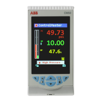
Description and function of the physical keys on the controller's front panel.
Recommendations for locating the controller to ensure optimal performance and safety.
Detailed instructions for making electrical connections to the controller.
Overview of the diagnostic status bar and its icons for monitoring controller status.
Detailed view of active diagnostic and alarm states, providing descriptions and tags.
Information on setting up passwords for Basic and Advanced access levels.
Configuration of setpoint values, including local, remote, and ramp settings.
Configuration of control types (PID, On/Off), autotune, and gain scheduling.
Configuration of basic device parameters, including initial setup and security.
Configuration of analog and digital inputs, outputs, and relays.
Configuration of setpoints, control loops, and output actions.
Configuration of up to 8 independent process alarms, including types and sources.
Viewing diagnostic and performance data, including messages and corrective actions.
Overview of basic control templates like Single Loop and Remote Setpoint.
Description of standard templates such as Auto/Manual and Analog Backup stations.
Details on advanced templates including Feedforward and Cascade control.
| Model | CM30 |
|---|---|
| Mounting | Panel Mount |
| Control | PID, ON/OFF |
| Output Channels | 3 |
| Housing Material | Plastic |
| Type | Process Controller |
| Input Types | Thermocouple, RTD, mA, mV, V |
| Output Types | Relay, SSR, mA |
| Communication Protocols | Modbus RTU |
| Power Supply | 100 to 240 V AC, 24 V AC/DC |
| Display | Dual 4-digit LED |
| Input Channels | 1 |
| Protection Class | IP66 |