ControlMaster CM30, CM50 and CMF310
Universal process controllers,
1
/4,
1
/2 DIN and fieldmount 4 Installation
20 IM/CM/ED–EN Rev. X
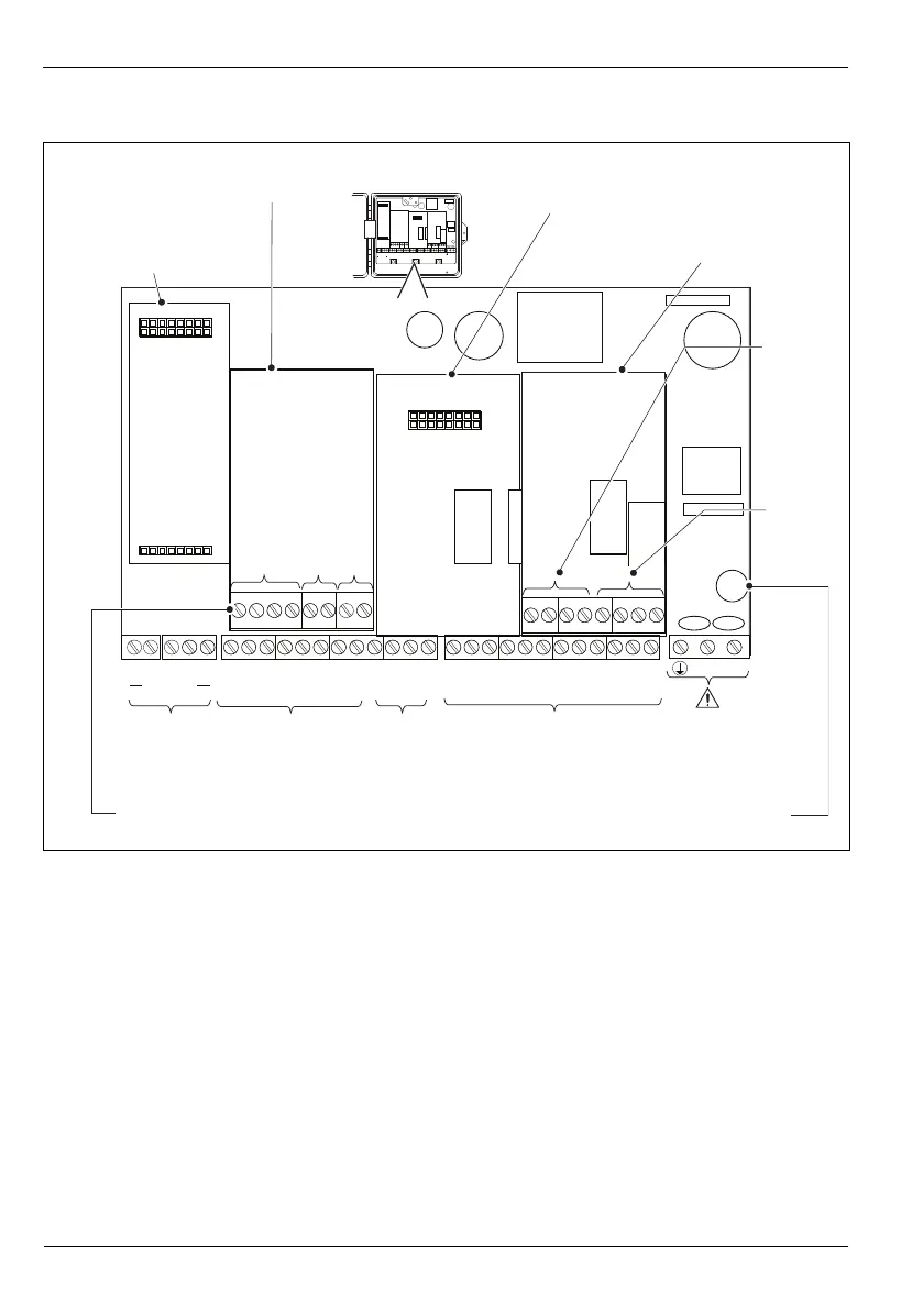
4.6.5 CMF310 Electrical Connections
Fig. 4.19 CMF310 Electrical Connections
COMMS
OUT 1 OUT 2
RELAY 1 RELAY 2 RELAY 3 RELAY 4
NL
INT
+24V
DIO1
DIO2
DIO3
DIO4
DIO5
DIO6
DIO COM
N/O
COM
N/C
N/O
COM
N/C
N/O
COM
N/C
N/O
COM
N/C
COMMUNICATIONS
MODULE
I/O MODULE 3
SK1
SK4
Input 1 Input 2 Tx PSU
SK5
SK2
12
+–+–
COMMS
OUT 1 OUT 2
RELAY 1 RELAY 2 RELAY 3 RELAY 4
NL
INT
+24V
DIO1
DIO2
DIO3
DIO4
DIO5
DIO6
DIO COM
N/C
COM
N/C
N/C
COM
N/C
N/C
COM
N/C
N/C
COM
N/C
COMMUNICATIONS
MODULE
I/O MODULE 2 I/O MODULE 3
SK1
SK4 SK5
SK2
1234
+–+–
5
I/O MODULE 3
SK5
RELAY
5
OUT 3 OUT 4
RELAY
6
COM
N/C
COM
N/C
+
–
+
–
I/O MODULE 3
SK5
RELAY
5
OUT 3 OUT 4
RELAY
6
COM
N/C
COM
N/C
+
–
+
–
345
Digital I/O
connections
Analog input module 1 terminal connections
Optional
communications module
(Ethernet / MODBUS)
Comms.
connections
Analog output
connections 1 and
2 (standard)
Analog input I/O module 1
(shown fitted)
I/O module 3 option
card (shown fitted)
Analog input I/O
module 2 position
Analog outputs
3 and 4 (optional)
Relay connections
5 and 6 (optional)
Fuse 3.15 A Type T 100 to 240 V, 50/60 Hz
Relay connections
1 to 4 (standard)
Mains supply 100 V to
240 V AC ±10 % (90 V
min. to 264 V max.)
50 / 60 Hz