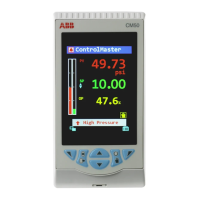
ControlMaster CM30, CM50 and CMF310
Universal process controllers,
1
/
4
,
1
/
2
DIN and fieldmount Contents
IM/CM/ED–EN Rev. X 1
Contents
1 Safety ............................................................................................................................................... 3
1.1 Electrical Safety ....................................................................................................................... 3
1.2 Symbols .................................................................................................................................. 3
1.3 Health & Safety ........................................................................................................................ 3
2 Introduction ...................................................................................................................................... 4
2.1 EC Directive 89/336/EEC ........................................................................................................ 4
2.2 End of Life Disposal ................................................................................................................. 4
2.3 UL Class I, Division 2 (CMF310 only – when ordered) .............................................................. 4
2.4 UL Class I, Division 2 (CMF310 si commandé) ......................................................................... 4
3 Display Overview ............................................................................................................................. 5
3.1 Front Panel Keys ..................................................................................................................... 6
4 Installation ........................................................................................................................................ 7
4.1 Siting ....................................................................................................................................... 7
4.2 Dimensions .............................................................................................................................. 8
4.2.1 CM30 Controller ............................................................................................................ 8
4.2.2 CM50 Controller ............................................................................................................ 8
4.2.3 CMF310 Controller – Panel-, Pipe- and Wall-mount Dimensions ................................... 9
4.2.4 CMF310 Weathershield – Pipe- and Wall-mount Installations ...................................... 11
4.3 Mounting ............................................................................................................................... 12
4.3.1 CM30 and CM50 Controllers ....................................................................................... 12
4.3.2 CMF310 Controller ...................................................................................................... 12
4.4 Jumper Links for Relay Outputs – CM30 and CM50 Controllers ............................................ 13
4.4.1 Removing the Controller
from its Case – CM30 and CM50 ................................................................................ 13
4.4.2 Resetting Jumper Links –
CM30 and CM50 ....................................................................................................... 13
4.5 Accessing the Connection Board – CMF310 Controller ......................................................... 14
4.6 Electrical Connections ........................................................................................................... 15
4.6.1 CM30 Electrical Connections ....................................................................................... 16
4.6.2 CM50 Electrical Connections ...................................................................................... 17
4.6.3 Analog Inputs – CM30 and CM50 Controllers .............................................................. 18
4.6.4 Digital Input / Output – CM30 and CM50 Controllers ................................................... 19
4.6.5 CMF310 Electrical Connections .................................................................................. 20
4.6.6 Analog Inputs – CMF310 Controllers ........................................................................... 21
4.6.7 Digital Input / Output, Relays and Analog Output Connections –
CMF310 Controllers .................................................................................................... 22
4.6.8 Frequency / Pulse Input (All Controllers) ....................................................................... 22
5 Operator Level Menus ................................................................................................................... 23
5.1 Diagnostic Status Bar ............................................................................................................ 23
5.2 Diagnostic View ..................................................................................................................... 24
5.3 Security Options .................................................................................................................... 24
5.4 Access Level ......................................................................................................................... 24
5.5 Profile Operator page ............................................................................................................ 25
5.5.1 Profile Operator page menu functions .......................................................................... 25
5.6 Operator page overviews ...................................................................................................... 26
6 Basic Level ..................................................................................................................................... 28
 Loading...


