High-speed counters,
CL-DC1, CL-DC2
123
1SVC 440 795 M0100
Function of the frequency counter
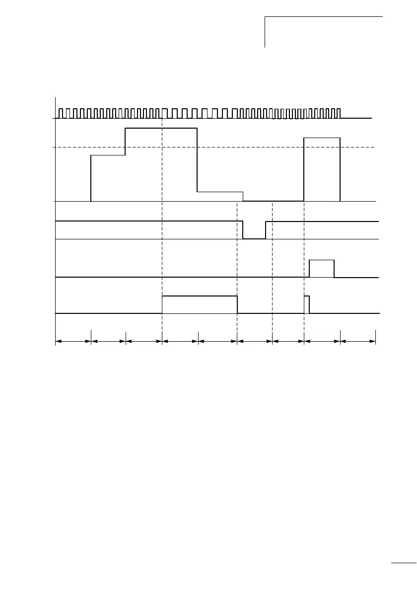
Figure 55: Signal diagram of frequency counter
1: counter input I3 or I4
2: upper setpoint
3: enable coil CC…
4: reset coil RC…
5: contact (n/o contact) C… upper setpoint value reached.
t
g
: gate time for the frequency measurement
• Range A: The counter is enabled. After a frequency above the
setpoint was measured for the first time, contact C15 (C16)
switches.
• Range B: If the actual value falls below the setpoint, the contact
is reset. The removal of the enable signal resets the actual value
to zero.
• Range C: The counter is enabled. After a frequency above the
setpoint was measured for the first time, contact C15 (C16)
switches.
• Range D: The reset coil resets the actual value to zero.
1
2
3
t
g
t
g
t
g
t
g
t
g
t
g
t
g
t
g
4
5
t
g
A
BC
D
 Loading...


