Connecting the inputs
41
1SVC 440 795 M0100
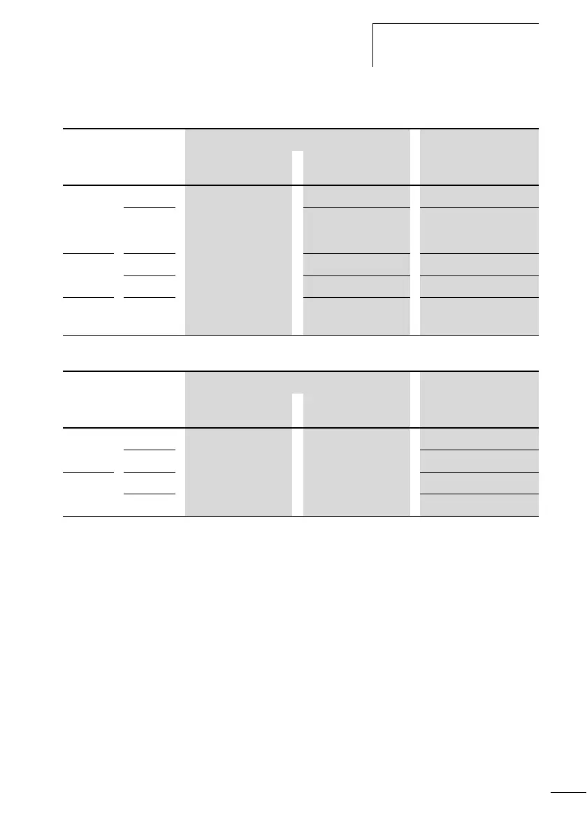
Table 3: Input signal values CL-DC2
Table 4: Input signal values CL-DC1
Connect analog DC inputs
The CL-AC1, CL-AC2 and CL-DC2 basic units are provided
with analog inputs. Inputs I7 and I8, and if present I11 and
I12, can be used to connect analog voltages ranging from 0
V to 10 V. A simple additional circuit also allows the analog
evaluation of currents from 0 to 20 mA. The analog input
signals are converted to 10-bit digital signals.
The following signals apply:
• 0 V DC corresponds to a digital 0.
• 5 V DC corresponds to a digital value of 512.
• 10 V DC corresponds to a digital value of 1023.
Voltage range of the input signals Input current
OFF signal ON signal
CL-LSR/
CL-LST/
CL-LMR/
CL-LMT
I1 to I6
0 to 5 V 15 to 28.8 V 3.3 mA at 24 V DC
I7, I8 greater than 8 V DC 2.2 mA at 24 V
CL-LMR/
CL-LMT
I9, I10
15 to 28.8 V 3.3 mA at 24 V DC
I7, I8 greater than 8 V DC 2.2 mA at 24 V
CL-LER/
CL-LET
R1 to
R12
15 to 28.8 V 3.3 mA at 24 V DC
Voltage range of the input signals Input current
OFF signal ON signal
CL-LSR/
CL-LMR
I1 to I6 0 to 4 V DC 8 to 15.6 V DC 3.3 mA at 12 V
I7, I8 1.1 mA at 12 V
CL-LMR I9, I10 3.3 mA at 12 V
I7, I8 1.1 mA at 12 V
 Loading...


