Wiring with the logic relay
74
1SVC 440 795 M0100
Relays, function relays
The logic relay has different types of relay for wiring in a
circuit diagram.
You can set the switching behaviour of these relays by
means of the coil functions and parameters selected.
h
In order to ensure compatibility with the AC010 devices,
each CL-LSR/CL-LST and CL-LMR/CL-LMT logically
supports all relay types internally. If a relay type is not
supported by the device, the switching state of the
contacts is always set to zero. The switching states of
contacts (n/o) and time switches are always logically zero.
This feature enables the same circuit diagram to be used
on all CL-AC1, CL-AC2, CL-DC1 and CL-DC2 devices.
Furthermore, you can use outputs that are not physically
present as markers.
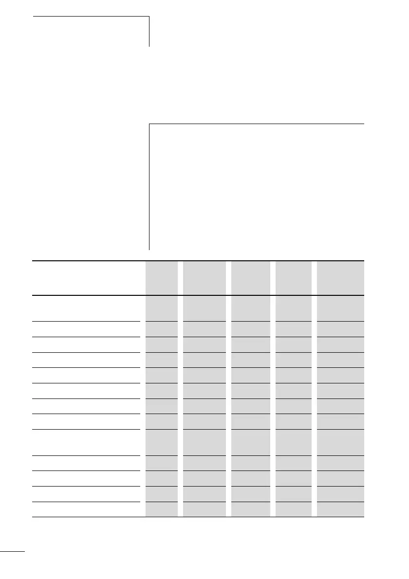
Relay CL
display
CL-LSR
CL-LST
CL-LMR
CL-LMT
Coil
function
Parameters
Analog value comparator
function relay
A A1…A16 A1…A16 – j
Counter function relay
C C1…C16 C1…C16 j j
Text marker function relay D D1…D16 D1…D16 j j
7-day time switch function relay Ö Ö1…Ö4 Ö1…Ö4 – j
Markers (auxiliary relay) M M1…M16 M1…M16 j –
Markers (auxiliary relay)
N N1…N16 N1…N16 j –
Operating hours counter O O1…O4 O1…O4 j j
CL output relay Q Q1…Q8 Q1…Q8 j –
CL output relay expansion,
marker
S S1…S8
(as marker)
S1…S8 j –
Timer function relay T T1…T16 T1…T16 j j
Conditional jump : :1…:8 :1…:8 j –
Year time switch Y Y1…Y8 Y1…Y8 – j
Master reset, (central reset) Z Z1…Z3 Z1…Z3 j –
 Loading...


