EasyManua.ls Logo

ABB CL-LMR 18AC2 Series User Manual

ABB CL-LMR 18AC2 Series
296 pages
To Next Page IconTo Next Page
To Previous Page IconTo Previous Page
Page #185 background imageLoading...
Page #185 background image
Wiring with the logic relay
182
1SVC 440 795 M0100
Alternatively the latching circuit can also be set up with the
wire break function using the “Set” and “Reset” coil
functions.
Coil Q1 latches if I1 is activated. I2 inverts the n/c contact
signal of S2 and only switches if S2 is activated in order to
disconnect the machine or in the event of a wire break.
Make sure that both coils are wired up in the correct order in
the CL circuit diagram: first wire the S coil and then the R
coil. This will ensure that the machine will be switched off
when I2 is actuated, even if I1 is switched on.
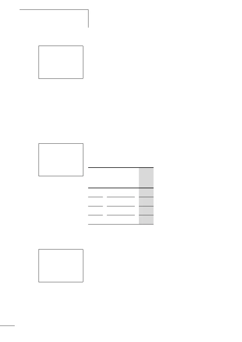
Impulse relay
An impulse relay is often used for controlling lighting, such
as stairwell lighting.
Table 23: Impulse relay
Cycle pulse on rising edge
You can create a cycle pulse on a rising edge if you use the
appropriate coil function.
This is very useful for count pulses, jump pulses.
I1-------SQ1
i2-------RQ1
S1 n/o contact at I1
S2 n/c contact at I2
I1-------äQ1
S1 n/o contact at I1
I1 Status of
Q1
Q1
00 0
01 1
10 1
11 0
I1-------ÈQ1
S1 n/o contact at I1

Table of Contents

Question and Answer IconNeed help?

Do you have a question about the ABB CL-LMR 18AC2 Series and is the answer not in the manual?

ABB CL-LMR 18AC2 Series Specifications

General IconGeneral
Rated Voltage250 V AC
CategoryRelays
Output2 c/o (SPDT) contacts
Terminal TypeScrew Terminal
Contact Configuration2 c/o (SPDT) contacts
Electrical Life100, 000 operations
Mechanical Life10, 000, 000 operations

Summary

Logic relay

Installation

Danger of electric shock

Highlights crucial safety rules to prevent electrical hazards during installation.

Connecting the power supply

Explains the procedures for connecting AC and DC power supplies to the logic relay.

Connecting the inputs

Guides on wiring various types of digital and analog inputs to the logic relay.

Connecting outputs

Explains how to connect relay and transistor outputs to loads like contactors and motors.

Commissioning

Creating your first circuit diagram

Offers a step-by-step guide to wiring and creating a basic CL circuit diagram.

Wiring with the logic relay

Analog value comparator/threshold value switch

Explains the use of analog comparators for threshold switching and comparing input values.

CL settings

Password protection

Covers setting up password protection for unauthorized access to the logic relay.

Retention (non-volatile data storage)

Explains how actual values and settings are retained after power loss or device reset.

Inside the logic relay

Monitoring of short-circuit/overload with CL-LST, CL-LMT and CL-LET

Details how to monitor outputs for short-circuits or overloads using internal inputs.

CL-SOFT

CL-SOFT

Introduces the PC software for creating, storing, test and managing CL circuit diagrams.

What happens if …?

Possible situations when creating circuit diagrams

Provides troubleshooting steps for common issues encountered during circuit diagram creation and operation.

Appendix

Technical data

Contains comprehensive technical specifications covering environmental, mechanical, and electrical data.

Related product manuals