Wiring with the logic relay
128
1SVC 440 795 M0100
Function of the high-speed counter function block
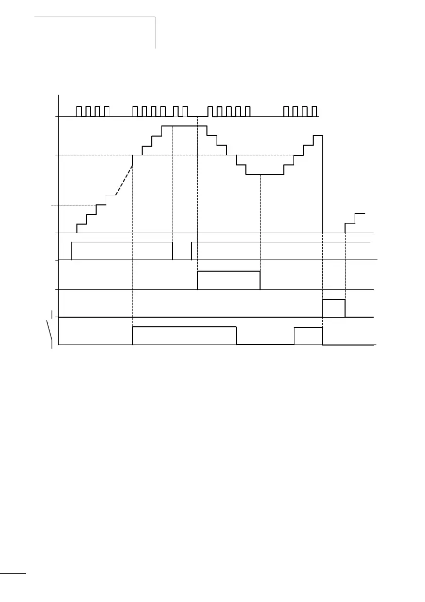
Figure 56: Signal diagram of high-speed counter
1: count pulses at counter input I1(I2)
2: setpoint of the counter
3: actual value of the counter
4: enable of the counter, CC13 (CC14)
5: count direction, direction coil DC13 (DC14)
6: reset coil of the counter RC13 (RC14)
7: contact of the counter, C13 (C14)
1
2
.........
.........
3
4
5
A
BC
D
E
.........
0
1
2
3
4
F
6
7
 Loading...


