Wiring with the logic relay
156
1SVC 440 795 M0100
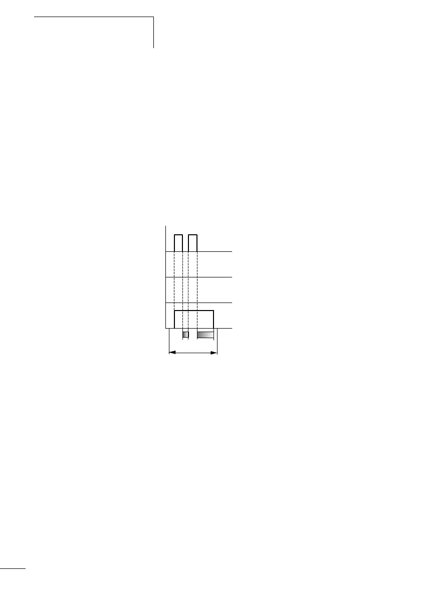
1: Trigger coil TTx
2: Stop coil HTx
3: Reset coil RTx
4: Switching contact (n/o contact) Tx
t
s
: Setpoint time
• Range A: The time elapses after the trigger coil is deactivated.
• Range B: The stop coil stops the time from elapsing.
• Range C: The reset coil resets the relay and the contact. After the
reset coil drops out, the relay continues to work normally.
• Range D: The reset coil resets the relay and the contact when the
function block is timing out.
Figure 65: Signal diagram of timing relay, off-delayed
(with/without random switching with retriggering)
Range E: The trigger coil drops out twice. The actual time t
1
is
cleared and the set time ts elapses completely (retriggerable switch
function).
1
2
4
3
t
s
E
t
1
 Loading...


