Delay times for inputs
and outputs
231
1SVC 440 795 M0100
An input signal S1 must therefore be 15 V or 8 V (CL-DC1)
for at least 20 ms on the input terminal before the switching
contact will change from 0 to 1 (range A). If applicable, this
time must also include the cycle time (range B) since the
logic relay does not detect the signal until the start of a cycle.
The same time delay (range C) applies when the signal drops
out from 1 to 0.
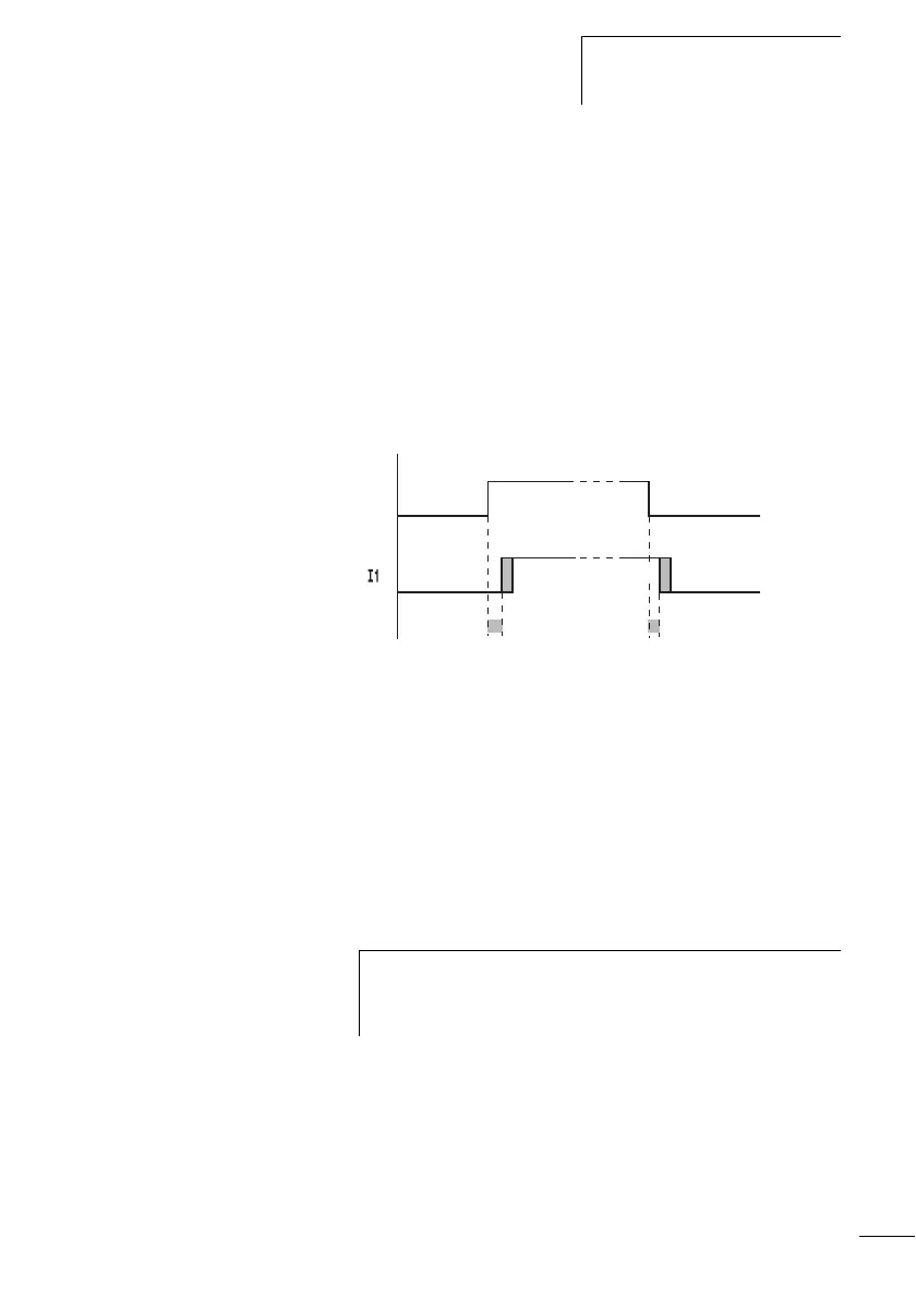
If the debounce is switched off, the logic relay responds to
an input signal after just 0.25 ms.
Figure 83: Switching behaviour with input debounce disabled
Typical delay times with the debounce delay switched off are:
• On-delay for I1 to I12:
– 0.25 ms (CL-DC2),
– 0.3 ms (CL-DC1)
•Off-delay for
– I1 to I6 and I9 to I12: 0.4 ms (CL-DC2), 0.3 ms (CL-DC1)
– I7 and I8: 0.2 ms (CL-DC2), 0.35 ms (CL-DC1)
1
0
1
0
S1
B
A
C
B
h
Ensure that input signals are noise-free if the input
debounce is disabled. The logic relay will even react to
very short signals.
 Loading...


