Installation
52
1SVC 440 795 M0100
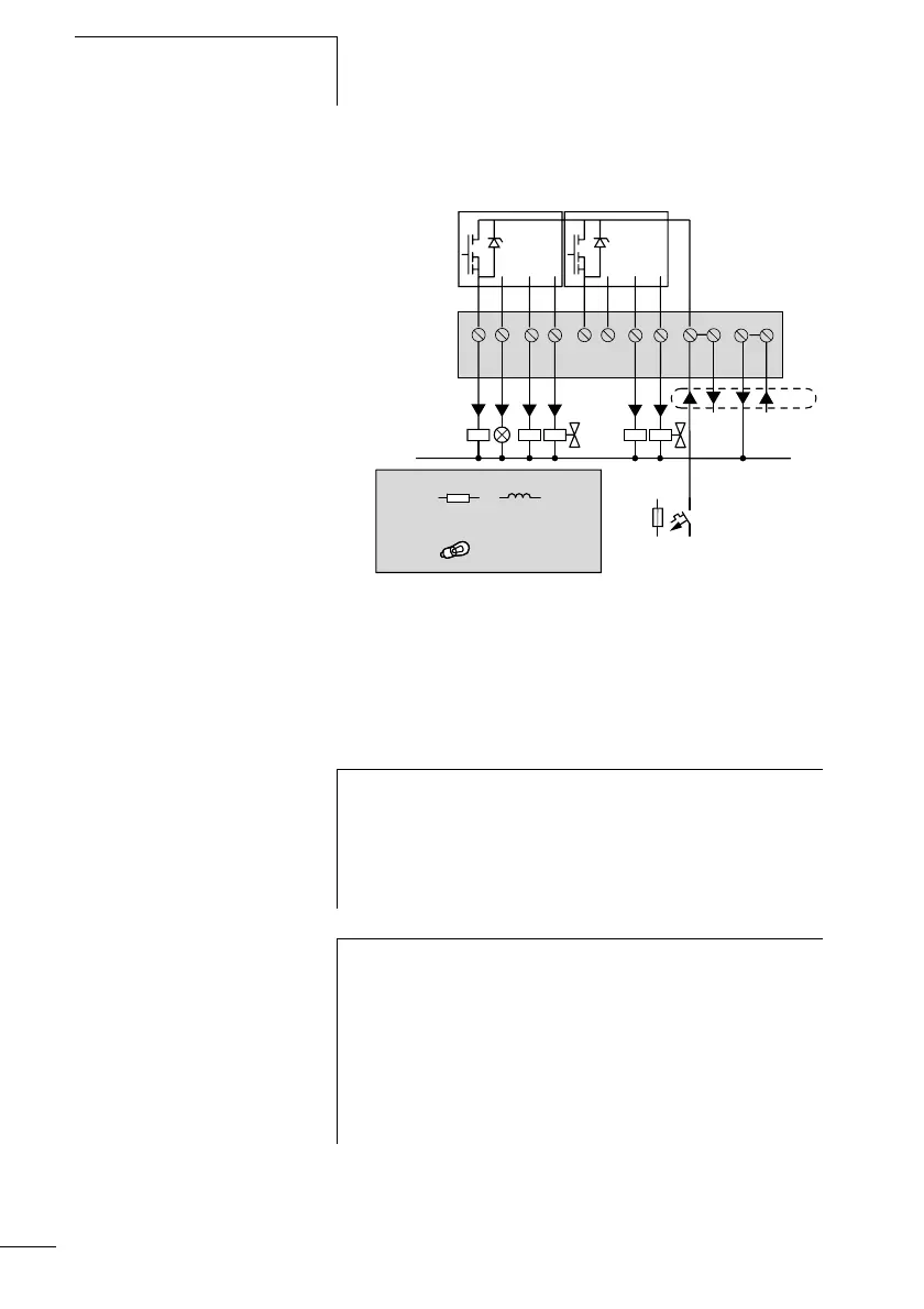
CL-LET.20DC2
Figure 32: Transistor outputs CL-LET.20DC2
Parallel connection:
Up to four outputs can be connected in parallel in order to
increase the output power. This enables a maximum output
current of 2 A.
0 V H
S1 S2 S3 S4 S5 S6 S7 S8 +24 V
f 2.5 A
F10 A
0V
+ 24 V H
R
5 W/24 V
0.5 A
(20.4 – 28.8 V H)
24 V H
0.5 A
Q
Q
i
Caution!
Outputs within a group (Q1 to Q4 or Q5 to Q8, S1 to S4 or
S5 to S8) can be switched in parallel; e.g. Q1 and Q3 or
Q5, Q7 and Q8. Outputs switched in parallel must be
activated at the same time.
i
Caution!
Please note the following when switching off inductive
loads.
Suppressed inductive loads cause less interference in the
entire electrical system. For optimum suppression the
suppressor circuits are best connected directly to the
inductive load.
 Loading...


