Setting the menu language
61
1SVC 440 795 M0100
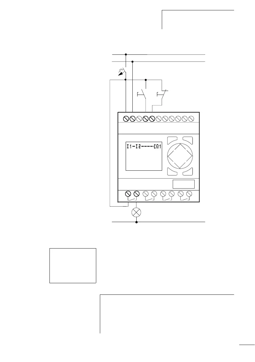
Figure 37: Lamp controller with logic relay
Starting point: the status display
The logic relay activates the status display after it is powered
up. This shows the switching state of the inputs and outputs,
and indicates whether the logic relay is already running a
circuit diagram.
1
2
Q1
H1
L01-
S1 S2
L01+
L01-
F1
+24V
0V
I1
I2
...........
I
MO 02:00
.......STOP
h
The examples were written without the use of expansion
units. If an expansion unit is connected, the status display
will first show the status of the basic unit and then the
status of the expansion unit before showing the first
selection menu.
 Loading...


