Commissioning
66
1SVC 440 795 M0100
X Press OK.
The tick changes to “STOP RUN
å”
The status display shows the current mode and the switching
states of the inputs and outputs.
X Change to the status display by pressing ESC and press
pushbutton actuator S1.
The contacts for inputs I1 and I2 are activated and relay Q1
picks up.
Power flow display
The logic relay allows you to check rungs in RUN mode.
This means that you can check your circuit diagram via the
built-in power flow display while it is being processed by the
logic relay.
X Switch to the circuit diagram display (confirm PROGRAM
menu with OK) and actuate pushbutton S1.
The relay picks up. The logic relay indicates the current flow.
X Press pushbutton actuator S2, that has been connected as
a n/c contact.
The rung is interrupted and relay Q1 drops out.
Press ESC to return to the status display.
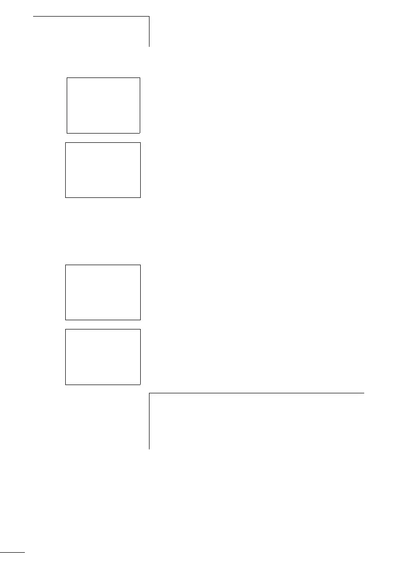
PROGRAM...Æ
STOP RUN
å
PARAMETER..
12..........
I
MO 02:00
1....... RUN
I1-I2----ÄQ1
I1-I2----ÄQ1
h
With the logic relay you can test parts of a circuit diagram
before it is entirely completed.
The logic relay simply ignores any incomplete wiring that
is not yet working and only runs the finished wiring.
 Loading...


