Wiring with the logic relay
72
1SVC 440 795 M0100
Coils
Coils are the actuating mechanisms of relays. In RUN mode,
the results of the wiring are sent to the coils, which switch
on or off accordingly. Coils can have seven different coil
functions.
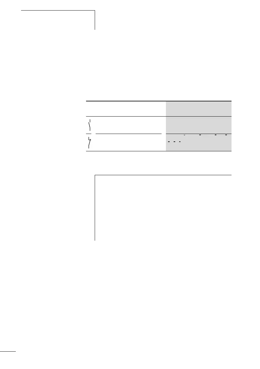
Table 5: Usable contacts
The logic relay works with different contacts, which can be
used in any order in the contact fields of the circuit diagram.
Contact CL display
n/o contact,
Open in the rest state
I, Q, M, N, A, Ö, Y, C, T, O, P, :,
D, S, R, Z
n/c contact,
Closed in the rest state
i, q, m, , a, ö, , c, t, , p, ,
, ,
N Y O
D
S R
Z
h
In order to ensure compatibility with the AC010 devices,
each CL-LSR/CL-LST and CL-LMR/CL-LMT logically
supports all possible contacts. The switching state is
always zero if contacts are not supported by the device,
i.e. devices without a clock. The switching states of
contacts (n/o) and time switches are always logically zero.
This feature enables the same circuit diagram to be used
on all CL-AC1, CL-AC2, CL-DC1 and CL-DC2 devices.
 Loading...


