INSTALLATION 19
The above is an example of the electrical
diagram of the contactor standard circuit of
different specifications, which may vary
according to product update or engineering
non-standard customization.
Operating state shown
The diagram illustrates the following conditions:
• Contactor open and in working position
• Circuits de-energized
• Fuse installed and not blown
Description of diagram figures
Fig.1 Control circuits of electrical latching
contactor
Fig.2 Control circuits of mechanical latching
contactor
Fig.3 VT Self-supplied circuit
Fig.4 Circuit of locking electromagnet on
contactor truck
Fig.5 Auxiliary contacts
Fig.6 Signaling circuit of contactor in the
racked-in and isolated position
Fig.7 Electric operation counter
Fig. 8 Electric-drive circuit for truck
Key symbols
□ =Reference number of the diagram figure
-XDB... =Connectors for the contactor circuits
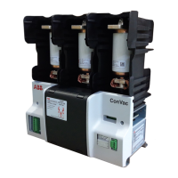
-QAC =Contactor
-SFC =Push-button or contact for contactor
closing
-SFO =Push-button or contact for contactor
opening
-KFA =Auxiliary control relay or contactor
-MBC =Closing coil
-AA =Power module
-PGC =Electrical operation counter
-BGF1,-BGF2 =Signaling contact for fuse status
-RiMe =Mechanical latching device
-BGB1...6 =Contactor auxiliary contacts
-BGT1 =Contacts for electrical signaling of
contactor in racked-in position
-BGT2 =Contacts for electrical signaling of
contactor in isolated position
-BGT3 =Contacts for electrical signaling of
truck status
-RLE2 =Locking magnet, when de-energized
it mechanically prevents contactor
from racking in or racking out
-T1 =Secondary coil of VT
-F301 =Protection fuse of VT secondary side
-X301 =Connection line
-MAT =Motorized truck of contactor
-RLM =Mechanical interlock (or equal)
Incompatibility
The circuits indicated by the following figures
cannot be supplied at the same time in the same
contactor:
1 – 2 2 – 3 4 – 8
Notes
A) The contactor is delivered complete with the
sole applications specified in the ABB order
confirmation. Consult the catalog of the
apparatus when making out the order.
B) Control command duration (-SFO and -SFC) at
rated voltage Ua Fig. 1 and Fig. 2: -SFC minimun
300 ms, -SFO minimum 300 ms.
-XDB
-QAC
49
-BGT2
51
52
53
54
6
-XDB71 -XDB71
-BGT2
57
58
-XDB71
-BGT2
53
54
-XDB71 -XDB71
-BGT1 -BGT1
9
10
4
1
2
5
3 6
24
2323
24
50
13
14
13
14
49
70170250
703
51
52
704705
706
53
54
57
70971058
-XDB
-XDB71
-XDB71 -XDB71
55
56
-XDB71
-BGT1
-XDB71
53
54
7
8
55
70770856
401