EasyManuals Logo
Home>ABB>Industrial Electrical>Cylon MATRIX-2 Series

ABB Cylon MATRIX-2 Series User Manual

ABB Cylon MATRIX-2 Series
28 pages
To Next Page IconTo Next Page
To Previous Page IconTo Previous Page
Page #8 background imageLoading...
Page #8 background image
Cylon® MATRIX-2 Series | Installation
©ABB 2023 All Rights Reserved.
Subject to change without notice
WWW.CYLON.COM
8
ATTACH RS-485 COMMUNICATION WIRES TO THE MS/TP SUBNET PORT
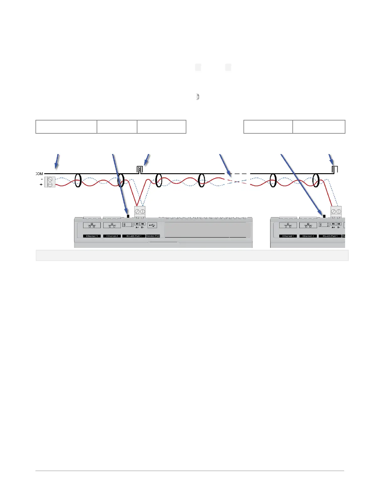
Wiring the RS-485 network involves connecting the A+ (95) and B- (96) terminals in a daisy-chained
configuration. One end of the network will be connected to the Fieldbus of the Network-level controller or
BACne router. At the other end of the network, the last device must be “terminated” by either installing a
100 120 resistor or, if the last device is a MATRIX-2, users can switch the MS/TP Subnet terminator
switch (located beside the MS/TP port) towards the
icon. This will effectively terminate the network.
The shield (screen) must be carried through the entire network, and must be grounded at one point on the
network as shown below:
Network-level Controller or
Router
MATRIX-2
Network Segment
end
- - - - - -
MATRIX-2
Network end
Shield connected at end
of network only
Network
Termination
switch set to
OFF
Shield continuous
throughout the
network
Network cable
segment daisy-chained
to next device
Network
Termination switch
set to ON at end of
network
Shield connected to
earth at one end of
network only
Note: If the RS-485 network is wired to an eSC, then the shield will be grounded at the eSC.

Questions and Answers:

Question and Answer IconNeed help?

Do you have a question about the ABB Cylon MATRIX-2 Series and is the answer not in the manual?

ABB Cylon MATRIX-2 Series Specifications

General IconGeneral
BrandABB
ModelCylon MATRIX-2 Series
CategoryIndustrial Electrical
LanguageEnglish

Related product manuals