II F 2-22
3ADW000072R0501_DCS600_System_description_e_e
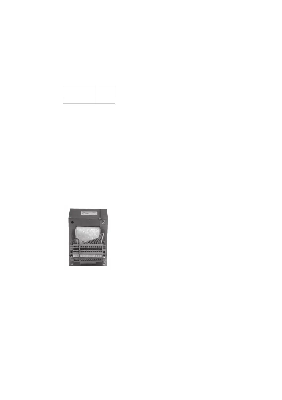
Auxiliary transformer T2 for electronic
system / fan supply
The converter unit requires various auxiliary voltages,
e.g. the unit’s electronics require 115 V/1-ph or 230 V/
1-ph, the unit fans require 230 V/1-ph or 400 V/690
V/3-ph, according to their size. The T2 auxiliary
transformer is designed to supply the unit’s electronic
system and all the single-phase fans including the fan of
the A5 converter.
Input voltage: 380...690 V/1-ph; 50/60 Hz
Output voltage: 115/230 V/1-ph
Power: 1400 VA
Fig. 2.6/5: T2 auxiliary transformer
Residual current detection
This function is provided by the standard software. If
needed, the analogue input AI4 has to be activated, a
current signal of the three phase currents should be
supplied to AI4 by a current transformer. If the addi-
tion of the three current signal is different from zero, a
message is indicated (for more information, see publi-
cation Technical Data).
Commutating reactor
When using the SDCS-FEX-2A field power converter,
you should additionally use a commutating reactor
because of EMC considerations. A commutating reac-
tor is not necessary for the SDCS-FEX-1 (diode bridge).
With DCF 503A/504A field power converters, it is
already installed.
Converter Reactor
≤≤
≤≤
≤500 V; 50/60 Hz
SDCS-FEX-2A ND 30
Table 2.6/4: Commutating reactor (for more information
see publication
Technical Data)