II F ii
3ADW000072R0501_DCS600_System_description_e_e
List of contents
II F SYSTEM DESCRIPTION
1 DCS 600 MultiDrive - the power converter II F 1-1
2 DCS 600 MultiDrive components overview II F 2-1
2.1 Environmental conditions .............................................. II F 2-3
2.2 DCS 600 power converter modules .............................. II F 2-4
2.3 DCS 600 overload withstand capability ........................ II F 2-7
2.4 Field Supply .................................................................. II F 2-9
2.5 Options for power converter modules ......................... II F 2-11
In-/output signals ........................................................ II F 2-11
Serial interfaces
Operation by the panel .............................................. II F 2-13
Panel (control and display panel) .............................. II F 2-14
Operation by the PC .................................................. II F 2-15
Drive control ............................................................... II F 2-15
2.6 Options ........................................................................ II F 2-17
Line reactors for armature (DCS600) and
field (DCF600) supply ................................................ II F 2-17
Aspects of fusing for armature circuits and field
supplies of DC drives .............................................. ...II F 2-19
Semiconductor type F1 fuses and fuse holders for
AC and DC power lines ............................................. II F 2-21
Fuses F3.x fuses and fuse holders for 2-phase
field supply ................................................................. II F 2-21
Transformer T3 for field supply .................................. II F 2-22
Commutating reactor ................................................. II F 2-22
Auxiliary transformer T2 for electronic system /
fan supply ................................................................... II F 2-22
Residual current detection ......................................... II F 2-22
EMC filters ................................................................. II F 2-23
3 Overview of Software (Vers. 15.xxx) ......... II F 3-1
3.1 Basic structure of DCS 600 MultiDrive .......................... II F 3-1
3.2 Control modes ............................................................... II F 3-1
3.3 Start, Stop and Fault reactions ..................................... II F 3-2
3.5 Torque control ............................................................... II F 3-4
3.4 Speed control ................................................................ II F 3-4
3.5 Torque control ............................................................... II F 3-4
3.6 HMI (Human Machine Interface) ................................... II F 3-4
3.7 Torque generation ......................................................... II F 3-5
3.7 Software diagrams ........................................................ II F 3-6
4 Connection examples ................................. II F 4-1
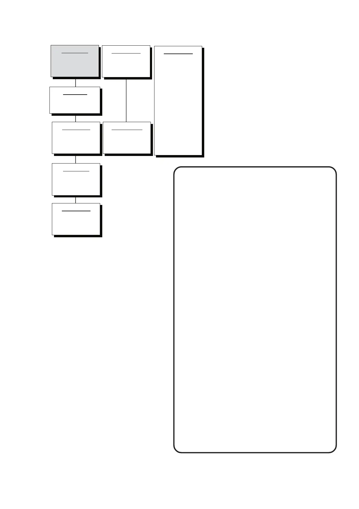
How the DCS 600 MultiDrive Documentation Sys-
tem works
This is to give you an overview how the system of
information for DCS 600 MultiDrive converters is
built up. The shaded part indicates the volume within
the total system you are just now working with. In
addition you see all other available documents for the
same system.
System Description
DCA 600 Enclosed
3ADW000121
Volume II F1
Oper. Instructions
DCS(F) 600
3ADW000080
Volume IV F
SW Description
DCS(F) 600
3ADW000076
Volume V F
Technical Data
3ADW000165
Volume III
System Description
DCS(F) 600
3ADW000072
Volume II F
Installation Man.
DCA 600 ...
3ADW000091
Volume VI F1
Service Manual
DCS 500/600
3ADW000093
Volume VI A
12-Pulse Manual
DCS 600
3ADW000115
Volume II F2