II F 4-2
3ADW000072R0501_DCS600_System_description_e_e
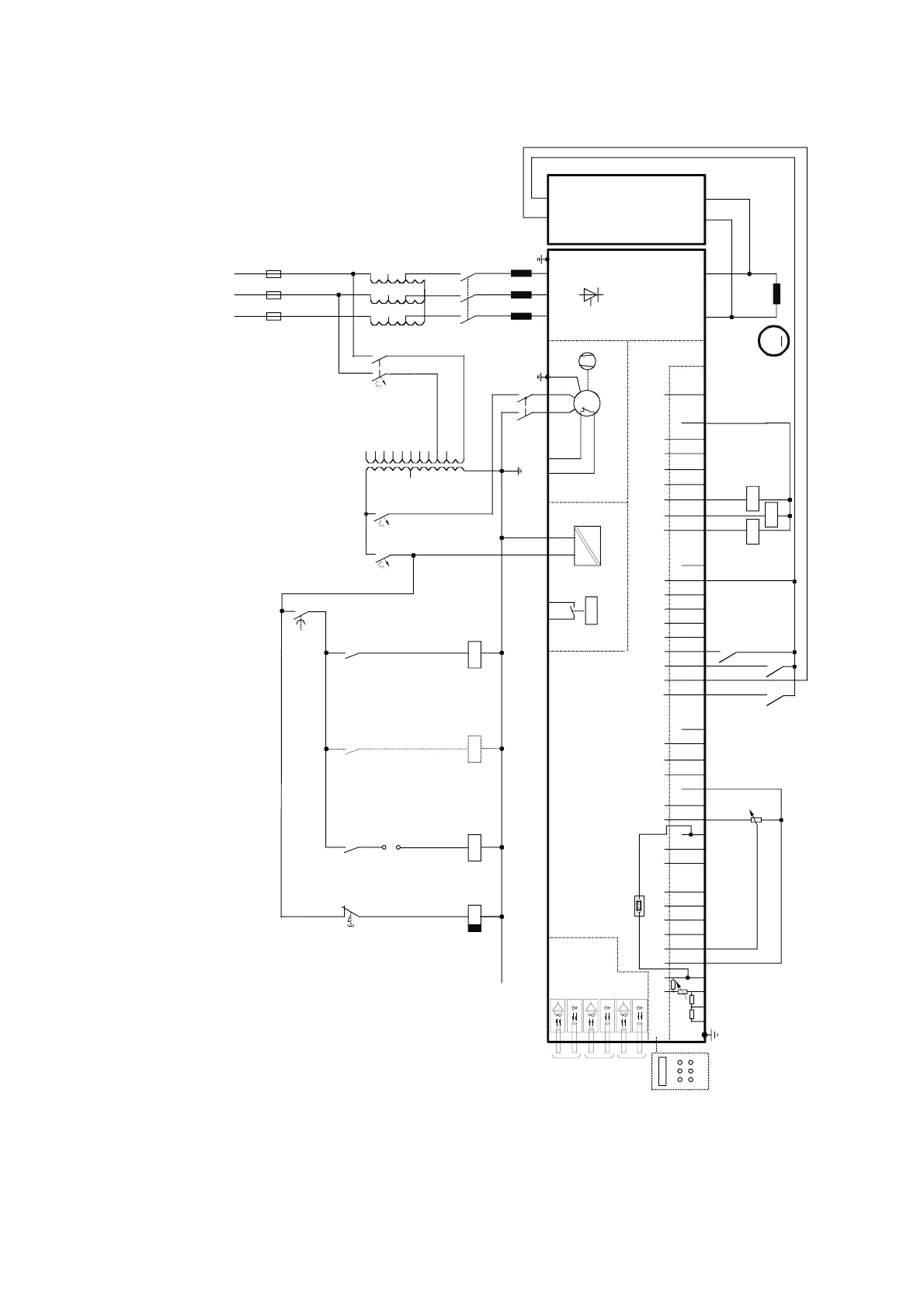
Fig. 4.2/1: DCF 600 Field supply converter wiring diagram
4.2 Field supply converter DCF 600
Note: In case the supply voltage for the excitation
is switched on the primary side of its supply
transformer additional overvoltage protec-
tion is required. Please contact ABB!
CH 0
X96:
DO8
12 X99:12 X2:45 X2:1 2 3
U1 W1V1 PE X 4 : 1 2
K1
L1 L2 L3
400V 50Hz
F1
K1
135
246
L1
M
~
F2
1
2
3
4
1
2
3
4
K5
F4 F5
1
2
1
2
T2
1
11
10
9
8
7
6
5
4
3
2
690V
660V
600V
575V
525V
500V
450V
415V
400V
380V
12
13
14
115V
230V
K16
K16
K5
X2:4
X2:5
K10
X33
PANEL
CDP 312
C 1 D 1
X11 X12
AITAC AI1
AI2 AI3
AI4
+10V -10V AO1 AO2 IACT DI1 DI2 DI3 DI4 DI5 DI6 DI7 DI8 +48V DO1 DO2 DO3 DO4 DO5 DO6 DO7
____
_
++++
+
M
0V
0V0V0V0V
X3:12345678910X4:12345678910X6:12345678910 X7:12345678 1...10
X5:
+
_
+
_
K1
K5
K11
K10
S4
56
K12
*
[K13]
K13
K12
CH 2
CH 3
K12
K16
DCF 506
DCF 600
AMC-DC 2
Control board (CON-2)
Power supply
(POW-1)
Field supply
converter
module
ELECTR.
DISCON-
NECT
depending on the unit type (C1, C2)
* if contactor relay
K13 is used
If SDCS-IOB-2
is in use K10,
K11 and K12
are not
necessary
Overvoltage
protection
K11 = Alarm