TRANSFORMER COMPONENTS
3
—
.
3. Installation
3.1 Comem eOLI
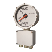
Insert the arm with float through the machined
hole on the conservator Place the o-ring on the
slot behind the gauge
(Fig.1/B) . Align the flange (Fig.1/C - stud length:
20±1 mm) with the threaded pins or holes
(Fig.1/A) (depending on the conservator flange
type). The gauge has to be assembled on the
flange using four screws M4x12 (Fig.1/D). The oil
level indicator flange has to be assembled using
the items showed in the table 1.
Table 1
Fig 1
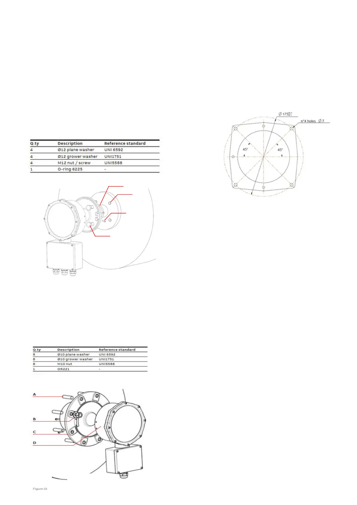
3.1 Comem eOLI22
Insert the arm with float through the machined
hole on the conservator. Place the o-ring in the
slot behind the flange (Fig.1/C). Insert the flange
on the threaded pins (Fig.1/A) of the conservator
flange and fix it with the items showed in the
table 2 (Fig.1/B). Fix the gauge on the flange
using 4 screws M4x12 (Fig.1/D).
3.3 Comem eViewer
Arrange the transformer with a dedicated place
following the scheme in the figure 3. The
connection can be done in two alternative way:
• threaded pin and nut M6
• screws M6
Fig.3
3.4 Modbus parameter
In order to implement a communication network
with eOLI/eOLI22 communicating in Modbus
RTU, the following communication parameters:
shall be considered:
-
Speed of data transmission (baud rate
): 9600
bits/s
-
Data bits (number of bits
): 8
-
Parity bit
: None
-
Stop bit
: 1
Fig.2
A
D
C
B
Table 2