S ELF - DEH Y DR ATI NG B R E ATH ER COM EM E S DB - INSTRUCTION MANUAL
2
—
4. Electrical connection
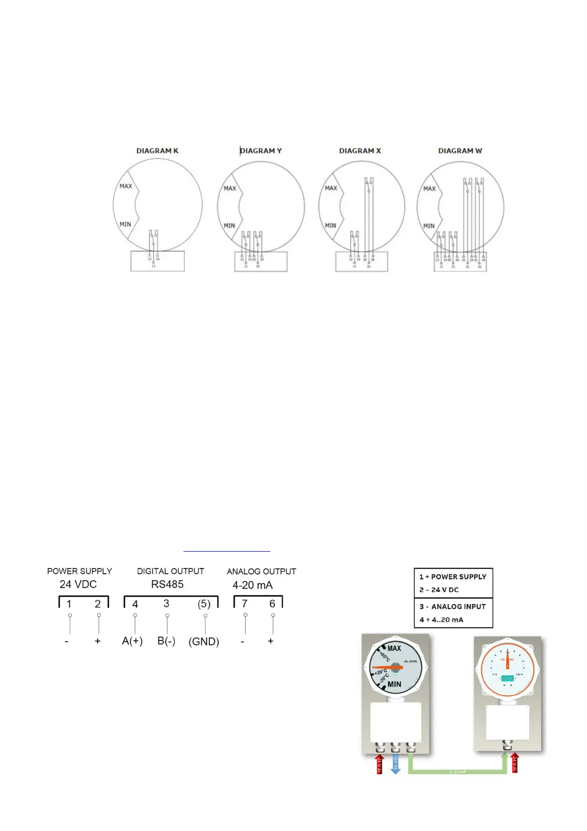
4.1 Micro switch wiring
Wire the electrical cables in accordance with the ordered
model following the electrical scheme
showed in the Fig.4.
4.2 Analog output and Modbus
communication wiring (Comem eOLI and
eOLI-22)
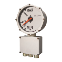
4.2.1 Power voltage
Connect the power voltage (as written on the
label on the terminal box cover – Fig.5) to
terminals 1-2 24 Vdc ±10% polarized
4.2.2 Analog output
Terminals for analog output 4-20 mA: 6-7
Maximum resistance: 450 Ω
4 mA = 0% (minimum arrow position)
20 mA = 100% (maximum arrow position)
4.2.3 Modbus communication
Digital output RS485: terminals 3-4
(for the Modbus register and address, check the
complete manual instruction Manual instruction)
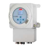
4.3 Comem eViewer wiring
4.3.1 Power voltage
Connect the power voltage (as written inside the
terminal box, Fig.5) to terminals 1-2.
24 Vdc ±10%
4.3.2 Analog input
Connect the analog signal (as written inside the
terminal box, Fig. 5) to terminals 6-7 4-20 mA:
- Negative Comem eViewer (3) with negative
Comem eOLI (7).
- Positive Comem eViewer (4) with positive
Comem eOLI (6)
4.3.3 Comem eViewer – Comem eOLI/eOLI22
connections
The following scheme (Fig.6) describes the
connections for signal remoting between an
electronic liquid level indicator and the eViewer.
Fig.4
Fig.5
Fig.6