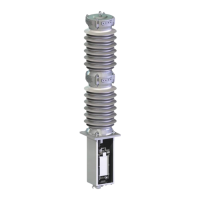
6.2.9. Jumper
complete discharge of capacitors. Setting the
supply disconnected and capacitors completely
discharged.
6.2.9.1. JP1001 –Standard Open / Protection Trip
Setting of BI Y4 to “Standard Open” or “Protection
trip” input
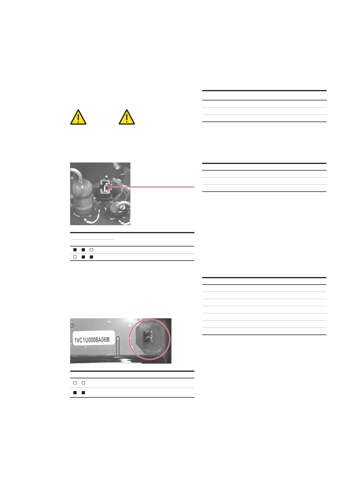
6.2.9.2. JP1019 – EnergY CONSUMPTION
reduced during the capacitor charging time. As a
result, the charging time is extended accordingly.
PRODUCT FAMILY: FSK II + - OPERATING AND MAINTENANCE MANUAL20 PRODUCT FAMILY: FSK II + - OPERATING AND MAINTENANCE MANUAL 20
1VSR630206EN – en – EDO-D0002852– Instruction manual – 2021.10 Design and specification are subject to change without notice
—
6. Technical Data
DANGER! IMPORTANT!
Function
Input active as protection trip
Input active as standard open
Table 13 Jumper 1001
Function
Standard energy consumption
ON
Reduced energy consumption
Table 14 Jumper 1019
Example of Jumper
6.3. Weights and Dimensions
accessories and do not include any specifications
for packaging.
6.5. Torques for tightening screws
and nuts
quality of 8.8 and an achieved permissible
6.6. Interfaces
6.6.1. Mechanical/Electrical
The general definition of the interfaces can be
taken from the associated, applicable dimensional
pole, the control box and to the layout of the main
6.6.2. Earthing Connections
The exact earthing positions of the apparatus can
be taken from the associated, applicable
6.4. Operating Conditions
Designation Weight [kg]
Outside Dimensions
W*D*H [mm]
)
Small Control box
)
Large Control box
)
Table 15 Approx. values
1
) for silicon insulators
2
) for ceramic insulators
3
Designation Value
Operating environment temperature
Altitude
Pressure
Table 16 Standard operation conditions
Thread Size Nominal Tightening Torque [Nm]
lubricated)