Additional explanation
No. 1: The input terminal for control supply voltage is 24 V DC. Its reference potential is the terminal right next to it,
labeled with '⊥'.
No. 2: For DOL-types there is only one control input, which starts the motor. For ROL-types, the 'R' terminal is for forward
running (right rotation), whereas the 'L' is for reverse running (left rotation) of the motor.
No. 3: For manual reset, press the reset button. Remote reset needs a connection of a button (N/O contact) between MAN an
RES terminals. After the overload function has tripped, the electronic compact starter can be reset automatically, manually
and remotely using these terminals. For manual or remote reset, connect a button (N/O contact) between the MAN and RES
terminals. Establish an electrical connection between the RES and AUT terminals for an automatic reset. (See chapter 5)
No. 4: The feedback relay is activated as soon as the electronic compact starter detects an error or indicates a message: the
N/O contact between terminals 96 and 97 is closed or the N/C contact between terminals 95 and 96 is opened.
No. 11: The main circuit output terminal must be connected with the motor.
No. 12: The main circuit input terminal must be connected with the 3-phase supply network. Please also establish short
circuit protection.
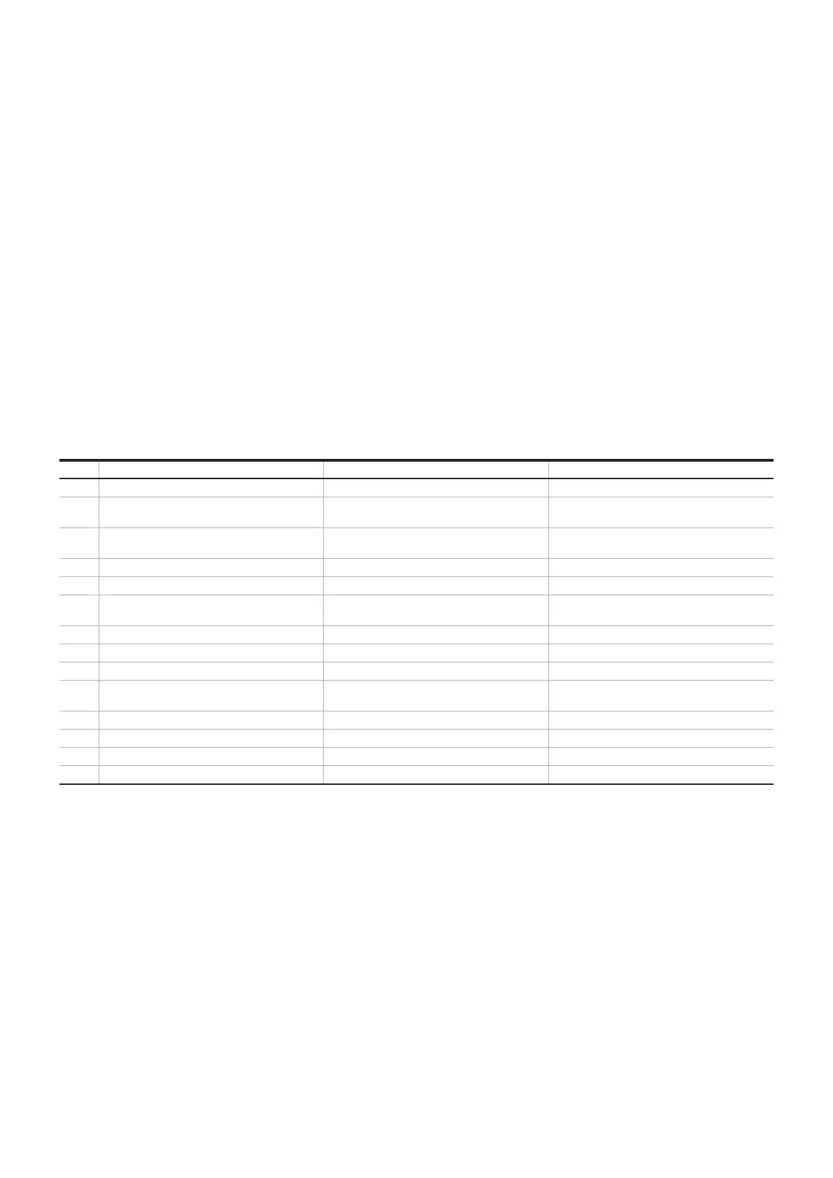
LED status indicators of DOLE- and ROLE- types
No. Indication HFxx-DOLE-24 V DC HFxx-ROLE-24 V DC
1 U
s
Input control supply voltage Input control supply voltage
2 DOLE: ON
ROLE: R, L
Connection point for ECD - external control
device for starting the motor
Connection point for ECD - external control
device Right /Left rotation
3 ⊥E Reference point control input
(emergency -stop)
Reference point control input
(emergency-stop)
4 MAN, RES, AUT Acknowledgement inputs Acknowledgement inputs
5 95,96,97 Control circuit fault signaling output Control circuit fault signaling output
6 Potentiometer Potentiometer for the rated operational
current "Ie" of the load
Potentiometer for the rated operational
current "Ie" of the load
7 PWR LED PWR LED (green) PWR LED (green)
8 ERR LED ERR LED (red) ERR LED (red)
9 Iadj LED Iadj LED (yellow) Iadj LED (yellow)
10 DOL: ON LED
ROL: R-, L-LED
ON LED (Rotation) R-LED (Right rotation)
L-LED (Left rotation)
11 Reset button Reset after trip Reset after trip
12 2/T1, 4/T2, 6/T3 Main circuit output Main circuit output
13 1/L1, 3/L2, 5/L3 Main circuit input Main circuit input
14 Metal latch Metal latch for fixation to the DIN rail Metal latch for fixation to the DIN rail
Table 3 HMI of DOLE, ROLE types
11 ELECTRONIC COMPACT STARTER | MANUAL