The associated electronics package is called the signal converter and may be either integrally or
remotely mounted. Typical integral MINI-MAG Magnetic Flowmeters are shown in Figures 1-1 & 1-2.
The integral housing shown contains a 50XM1000 electronics module. Remote models 10D1475J &
10D1475S are furnished with remote 50XM1000 electronics. Refer to the separate 50XM1000
converter instruction manual for additional information.
The flowmeter without the electronics package is used with a remote signal converter. A remote
mounted signal converter is recommended if:
• The integral model vibration specification is exceeded and/or
• The process liquid temperature exceeds the value given for that ambient
temperature listed in the integral model’s specifications.
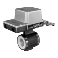
Figure 1-3 shows a remote Primary used for general purpose and FM Class I, Div.2 applications. A
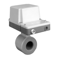
2-piece box with cable seal and pressure-relief fitting is shown. Figure 1-4 shows the remote Primary
with cable seal used for FM Class I, Div.1 applications.
The signal converter also contains a magnet-driver unit that is used to power the meter’s magnet
coils. The steady state magnetic field principle, referred to as the MAG-X
®
design concept, provides
optimum zero point stability at an optimized frequency which is a submultiple of the power line
frequency.
For additional details and a basic functional description, refer to Chapter 4.0.
FIGURE 1-3. 10D1475J REM.
PRIMARY w/ GEN. PURPOSE BOX
FIGURE 1-4. 10D1475J REMOTE
w/ EXPLOSION PROOF BOX
10D1475 MINI-MAG MAGNETIC FLOWMETER INSTRUCTION MANUAL
1-2 INTRODUCTION
 Loading...