Chapter 4 – Electrical Installation
4-2 NMBA-01 Installation and Start-up Guide
NMBA-01 Connections
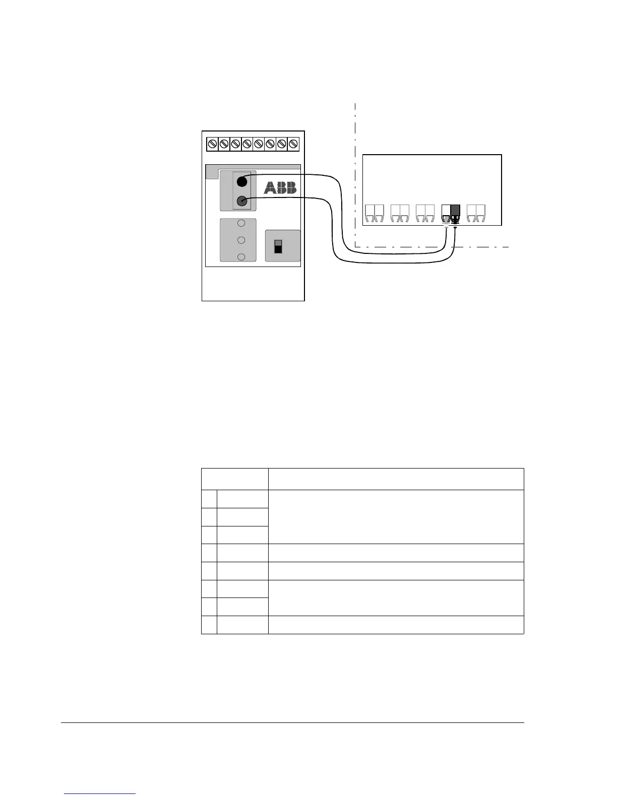
Figure 4-2 Fibre optic link connecting the NMBA-01 adapter
to the drive.
The NMBA-01 module is connected to the drive using a fibre optic
cable link. Consult the drive documentation as to the corresponding
terminals inside the drive.
The bus cable and the external power supply are connected to terminal
block X2 on the NMBA-01.
Table 4-1 Description of terminal block X2.
X2 Description
1D(P)
D(P) = B = Data Positive (Conductor 1 in twisted pair)
D(N) = A = Data Negative (Conductor 2 in twisted pair)
DG = Data Ground
2D(N)
3DG
4 SHF Cable screen AC earthing (via an RC filter)
5 SH Cable screen earthing (directly earthed)
6 0V
Power supply for the module (24 V d.c. ± 10 %); screened cable.
7 +24 V
8PEEarth
NMBA-01
MODBUS
ADAPTER
BUS
TERMINATION
ON
OFF
X2
PE SH SHF DG D(N) D(P)
TXD
RXD
XMIT
REC
ERROR
+24V 0V
ABB Drive
RT
12345678X2:
T
DDCS