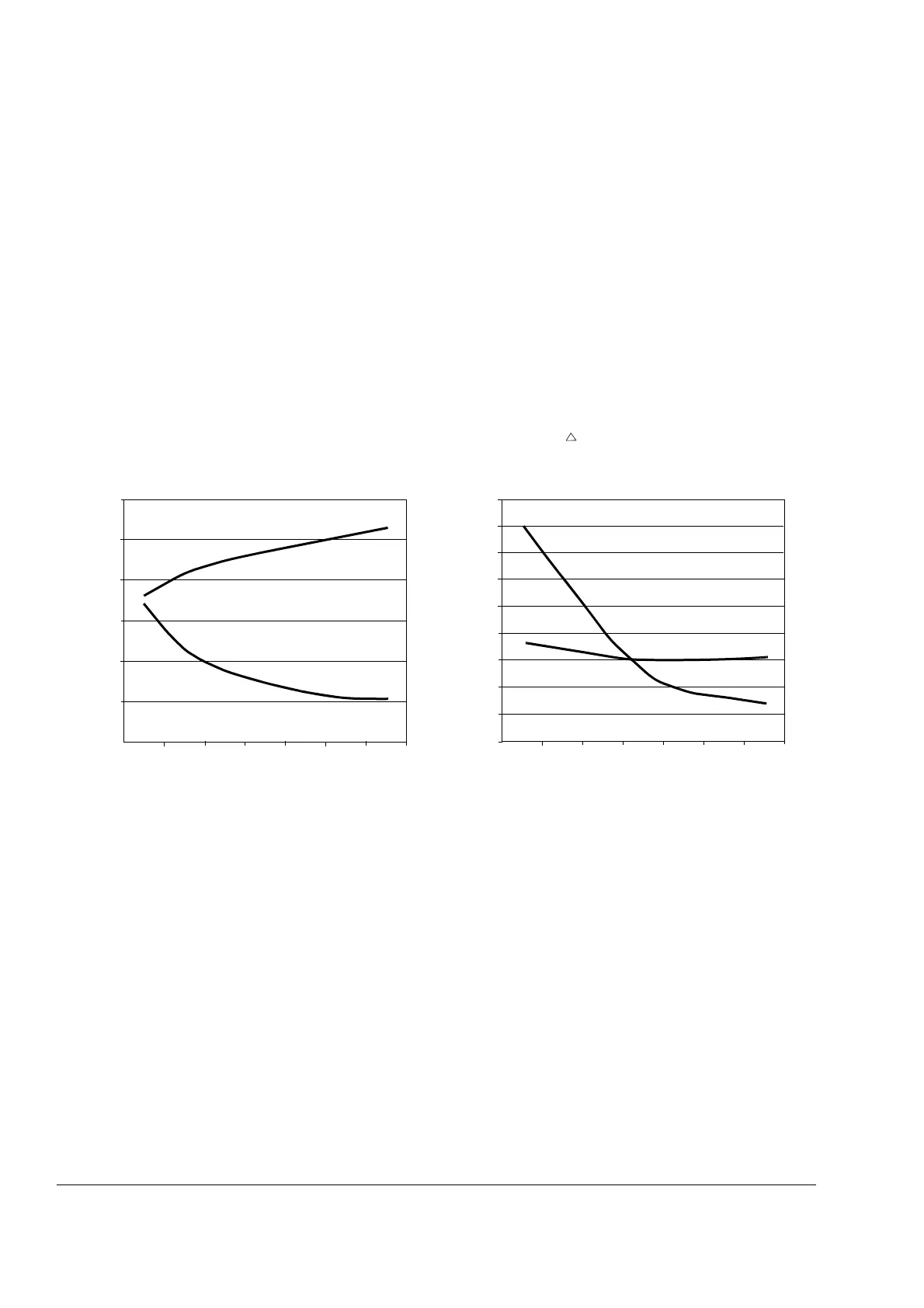
Operation principle
8
Graphs illustrating the effect of the du/dt filter
The graphs show the peak line-to-line voltage (Û
LL
) and voltage change (du/dt) at
the motor terminals as a function of the motor cable length.
Û
LL
and du/dt are scaled
to the nominal line-to-line voltage
(U
N
). To calculate the actual peak voltage value in
volts and du/dt value in volts per microsecond, multiply the values of the graph by
the supply voltage
(U
N
).
The values in the first graph are measured with an ABB du/dt filter while the second
graph without any output filtering. The values in the second graph are only
representative. The actual unfiltered du/dt values depend on the drive type, and are
usually in the range of 1 to 5 kV/microsecond.
In case of drives with an IGBT supply unit or resistor braking, the Û
LL
and du/dt
values are approximately 20% higher.
The voltage rise time can be calculated as follows: t = 0.8 · Û
LL
/(du/dt).
Û
LL
/U
N
Without du/dt Filter
Cable length (m)
du/dt
U
N
-------------(1/μs)
1.0
2.0
5.0
4.0
3.0
1.5
2.5
3.5
4.5
100 200 300
100 200 300
0.0
0.5
1.0
1.5
2.0
2.5
3.0
Cable length (m)
With du/dt Filter
du/dt
U
N
-------------(1/μs)
Û
LL
/U
N
5.5
 Loading...