1SCC303002M0204, rev. D
18
Installation and operating instructions, OTM_C
5. Connecting
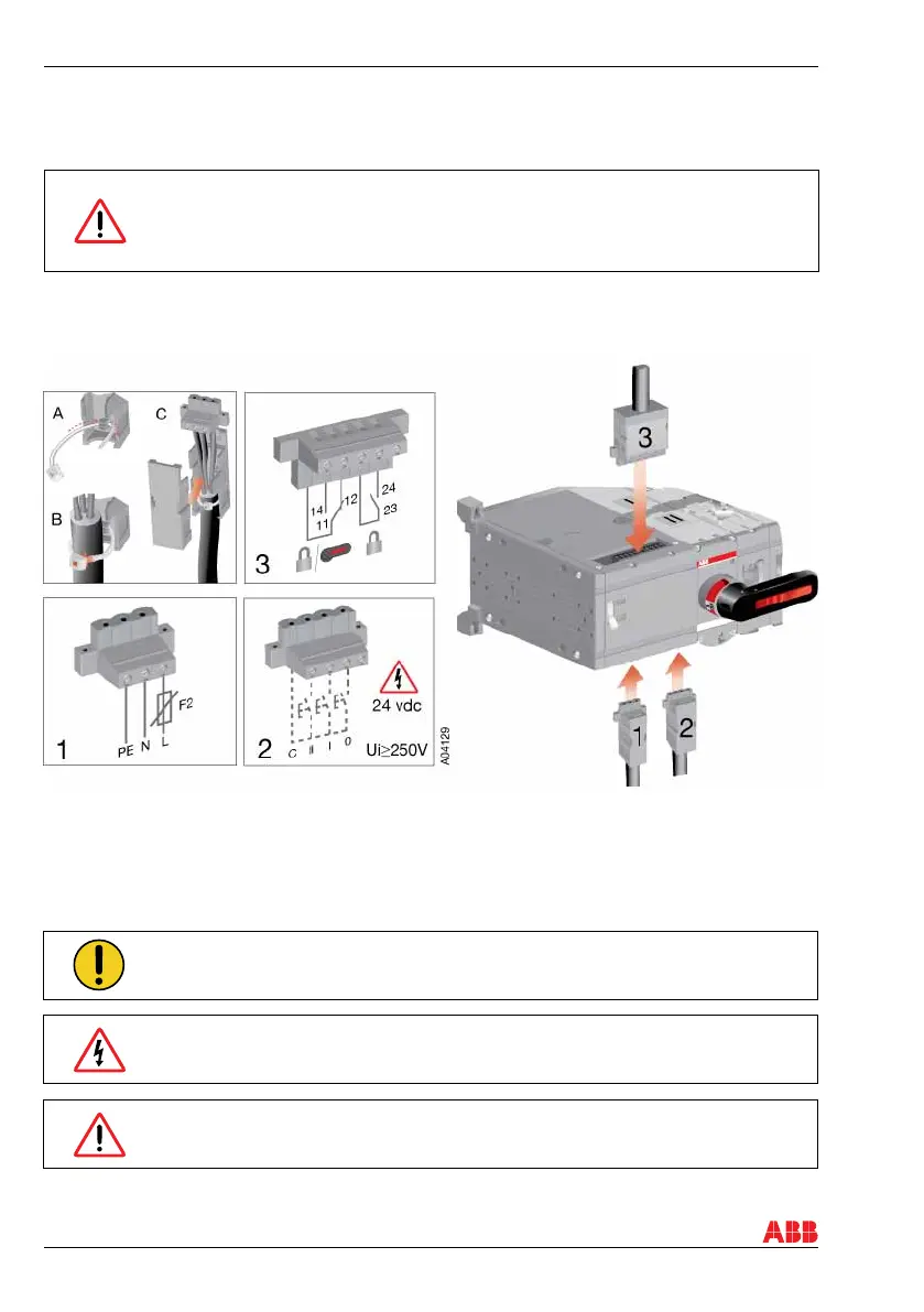
Figure 5.1 Motorized change-over switch terminals
1. Terminal for motor operator voltage supply
2. Control terminal for push buttons or selector switch
3. Terminal for state information of locking
Only an authorised electrician may perform the electrical installation and maintenance
of motorized change-over switches. Do not attempt any installation or maintenance
actions when a motorized change-over switch is connected to the electrical mains.
Before starting work, make sure that the change-over switch is de-energised.
5.1 Control circuit
The control voltage (output C = 24Vdc) on the control terminal is non-isolated, see
box 2 in Figure 5.1
When relay outputs are used with inductive loads (such as relays, contactors and
motors), they must be protected from voltage spikes using varistors, RC-protectors
(AC current) or DC current diodes (DC current).
Do not couple power for the control terminal. See the correct terminal for the power
supply in Figure 5.1
5. Connecting
 Loading...