2
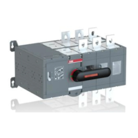
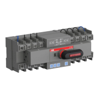
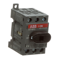
MOTORIZED CHANGE-OVER AND TRANSFER SWITCHES, OTM_C
—
Table of contents
1. Introduction 04
1.1 Use of symbols 04
1.2 Explanations of abbreciations and terms 04
2. Product overview 05
3. Quick start 06
3.1 Operating the motorized change-over
witch electrically: remote control 06
3.1.1 Locking electrical operation 07
3.2 Operating the motorized cahnge over switch
manually; local operation 08
4. Installation 09
4.1 Mounting the motorized change-over switch 09−10
5. Dimension drawings 11−17
6. Connections 18
6.1 Mounting postitions 19
6.2 Labelling 19
7. Connecting 20
8. Operating 21
8.1 Electrical operation 21−22
8.1.1 Impulse control 23
8.1.2 Continuous control 24
8.2 Manual operation by using the handle 25
8.3 Locking 26
8.3.1 Locking the electrical operation 26
8.3.2 Locking the manual operation 26−27
9. Technical data 28−29
10. Accessories 30
10.1 Terminal clamp sets OZXA_OTZB_ 30
10.2 Bridging bars OTZC_, OTZR_ 31−34
10.3 Voltage sensing connectors OMZB_ 35
10.4 Terminal shrouds OTS_ 36−37
10.5 Reversing bars OTZR_ 38
10.6 Voltage sensing connectors OMZB_ 39−40
10.7 Auxiliary contacts OA_ 41
10.8 Dual power sourse ODPS_ 42
10.9 Handle and spare fuse storage OTVS_ 43
11. Clearances per UL 1008 44
11.1 Phase barriers OTB_ 45−46