20
MOTORIZED CHANGE-OVER AND TRANSFER SWITCHES, OTM_C
—
7. Connecting
Only an authorised electrician may perform the electrical installation and maintenance of
motorized change-over switches. Do not attempt any installation or maintenance actions
when a motorized change-over switch is connected to the electrical mains. Before starting
work, make sure that the change-over switch is de-energised.
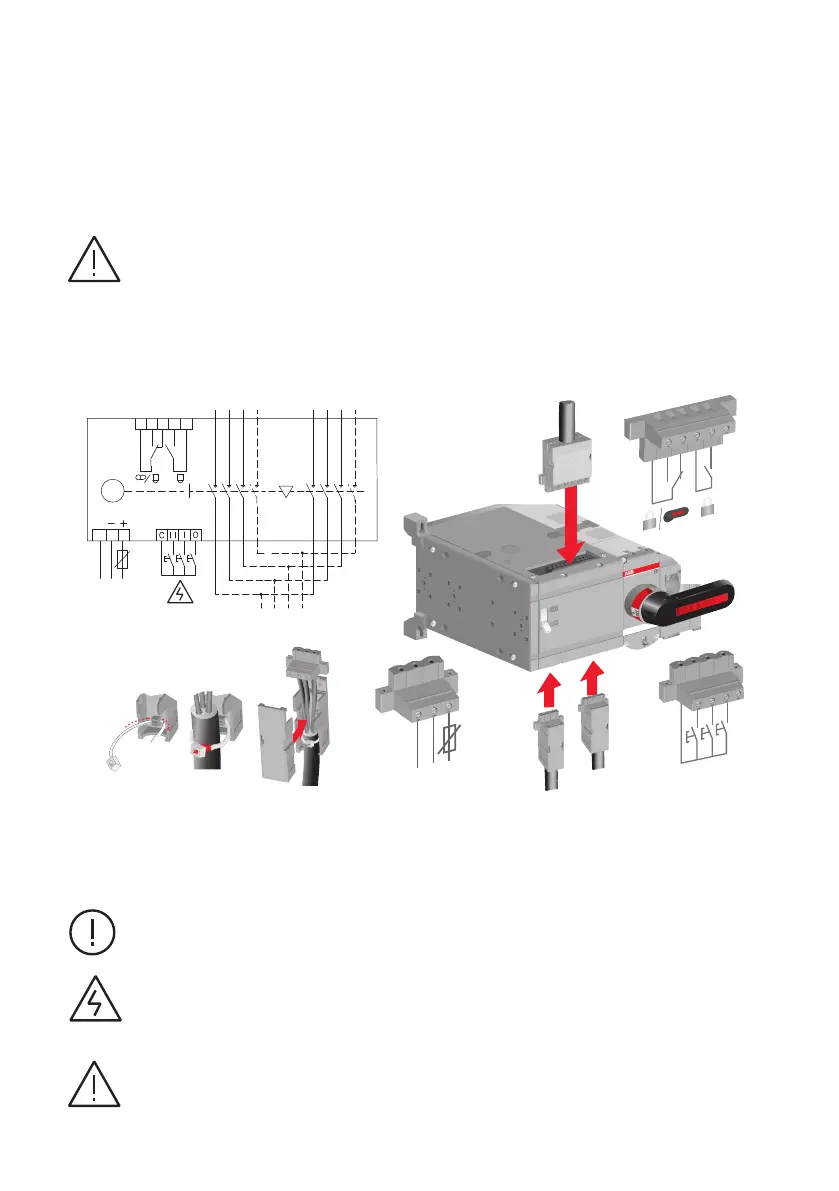
Figure 7.1 Motorized change-over switch terminals
1. Terminal for motor operator voltage supply
2. Control terminal for push buttons or selector switch
3. Terminal for state information of locking
—
7.1 Control circuit
Do not couple power for the control terminal. See the correct terminal for the power supply
in Figure 7.1
The control voltage (output C = 24Vdc) on the control terminal is non-isolated,
see box 2 in Figure 7.1
When relay outputs are used with inductive loads (such as relays, contactors and motors),
they must be protected from voltage spikes using varistors, RC-protectors (AC current) or
DC current diodes (DC current).
Information
Hazardous
voltage
Warning
Warning
II
M
M
Man.
Man.
M
M
Man.
Man.
I
PE
N
L
F2
C
II
I
0
A
2
B C
-
+
1
11
14
12
23
24
3
LOAD
1
2
LINE I
II
M
PE N L
F 2
11 14 12 23 24
Do not connect to
any power supply
24 vdc
 Loading...