27
MOTORIZED CHANGE-OVER AND TRANSFER SWITCHES, OTM_C
MOTORIZED CHANGE-OVER AND TRANSFER SWITCHES, OTM_C
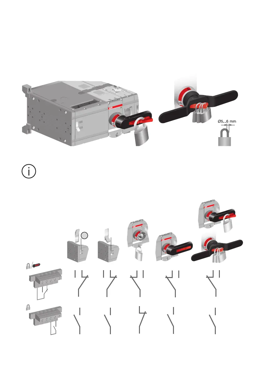
Figure 8.9 Locking state information
Figure 8.8 Locking the manual operation
The handle cannot be removed when padlocked to position 0.
The following figure shows the locking state information (the voltage on motor operator supply
needed).
M
M
Man.
Man.
M
M
Man.
Man.
Man.
M
M
Man.
Man.
M
14
12
11
23
24
23
24
23
24
23
24
23
24
23
24
11
1214
11
12
14
11
1214
11
12
14
11
12
14
II
I
M
M
Man.
Man.
M
M
Man.
Man.
Information
 Loading...