1SFC132081M0201 | Installation and commissioning manual | Connection 43
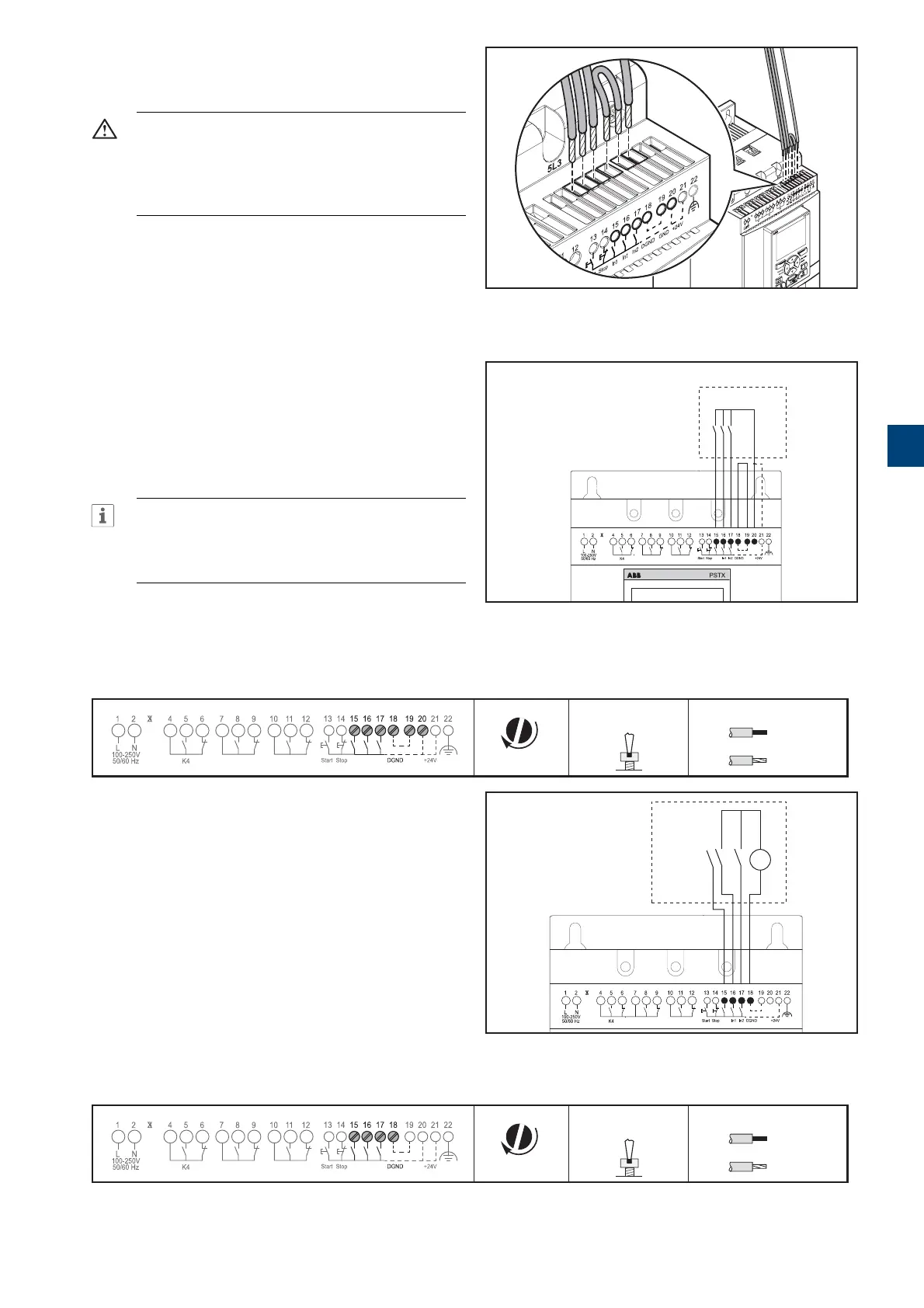
5.1.2.4 Programmable inputs - terminals 15, 16
and 17
WARNING
Use only 24 V DC to connect terminal 13, 14,
15, 16 and 17. Other voltages can damage the
Softstarter and the warranty will no longer be
valid.
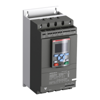
The Softstarter has 3 programmable inputs.
• In0, default reset event.
• In1, default none
• In2, default none
For programming the Softstarter inputs, see chapter 7.14
Inputs/outputs.
Connect the cables, see Figure 5.11, and Figure 5.12
to use the internal control supply voltage, or Figure 5.11
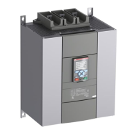
and Figure 5.13to use an external source.
INFORMATION
Connections for sequence start, see chapter
5.1.2.5 Programmable inputs (Sequence
start)
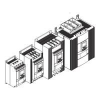
Tightening torques and cable dimensions.
0,2 .. 2,5 mm
2
2x0,2 .. 1,5 mm
2
0,2 .. 2,5 mm
2
2x0,2 .. 1,5 mm
2
AWG 12 ... 24
0,5 Nm
4,3 lb.in
3,5 x 0,6 mm
(0.138 x 0.024 in)
M3
L
100-250V
50/60 Hz K4 K5 K6
Start Stop In0 In1 In2 GND +24V
N
1SFC132081M0201
Tightening torques and cable dimensions.
0,2 .. 2,5 mm
2
2x0,2 .. 1,5 mm
2
0,2 .. 2,5 mm
2
2x0,2 .. 1,5 mm
2
AWG 12 ... 24
0,5 Nm
4,3 lb.in
3,5 x 0,6 mm
(0.138 x 0.024 in)
M3
L
100-250V
50/60 Hz K4 K5 K6
Start Stop In0 In1 In2 GND +24V
N
1SFC132081M0201
Figure 5.11
Terminals 16 and 17
1SFC132081M0201
Figure 5.12
Programmable inputs, terminals 15, 16 and 17
PSTX
L
100-250V
50/60 Hz K4 K5 K6
Start Stop In0 In1 In2 DGND +24V
N
GND
1SFC132081M0201
Figure 5.13
External control voltage
L
100-250V
50/60 Hz K4 K5 K6
Start Stop In1 In2 DGND +24V
N
DC
+
In0
GND
-
1SFC132081M0201
5