17
EN
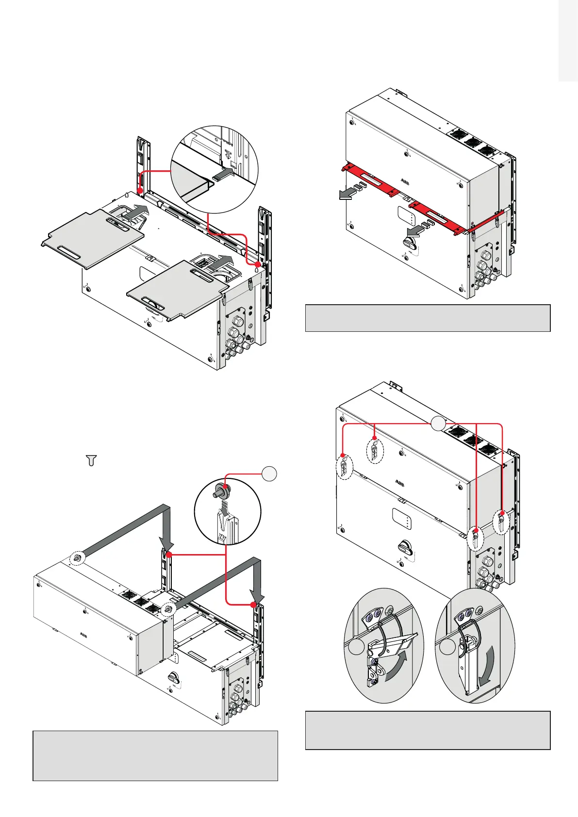
• Remove the handles (04) or eye bolts.
• Insert the two gasket protective covers sliding
the positioning pins (shown in red in the picture)
into the proper bracket (03) holes. If the mounting
is correct the gasket protective cover will have a
locked position.
PVS
• Lift the power module up to the bracket (03) and
over the wiring box, using the handles (04) or the
M8 eyebolts.
• Insert the heads of two rear attachment pins (17)
(placed on the rear part of the power module) into
the slots on the bracket (03).
PVS
17
ATTENTION – A Risk of injury due to the
heavy weight of the equipment. Always
consider the center of gravity of the
enclosures while lifting.
• Remove the previously installed gasket protective
covers from the inverter by slinding them pulling
from the handles.
PVS
NOTE – D Gasket protective covers and
handles can be reused for a new installation.
• Fasten all of the four side closures (latches) (16)
as shown in the pictures.
PVS
A
B
16
ATTENTION – A Risk of injury due to the
high strength of latches (16) Use the proper
protection gloves.

 Loading...


