22 Quick Installation Guide - PVS-175-TL “A.1 Version”
EN
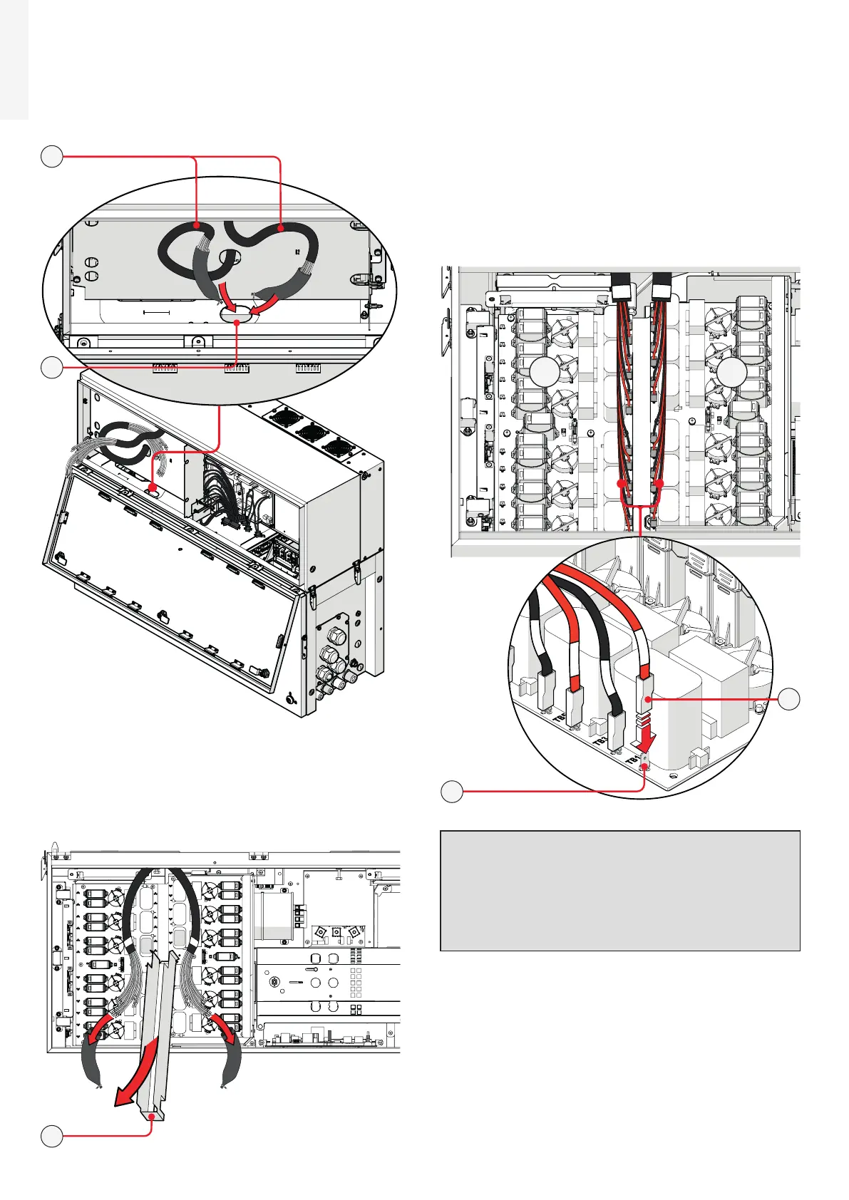
• Pass the DC interface cables (33) into the wiring
box using the dedicated opening for DC cables
(30) as shown in the picture.
33
30
• Close the power module cover (06) and open the
wiring box cover (07).
• Remove the cable sheathing from the DC interface
cables (33) and the DC cable duct (22) from the
DC surge arrester plate (21).
22
• Connect all DC interface cables (33) to the
related DC interface faston connectors (29)
located in the DC surge arrester plate (21).
The two cable group are marked with a
identification label “B1” and “B2” that corresponds
to the DSP board number label (“B1” and “B2”).
Each single cable are marked with a label
corresponding to related DC interface faston
connectors (29) on the DSP boards (E.g. “TB1”,
“TB3”...).
29
33
B2
B1
WARNING – B Polarity inversion can cause
serious damage. Check polarity before
connecting each cable!
WARNING – B Always check correspondance
of cables and board faston connectors
identification!

 Loading...


