ABB REL 356 Current Differential Protection
5-25
Testing
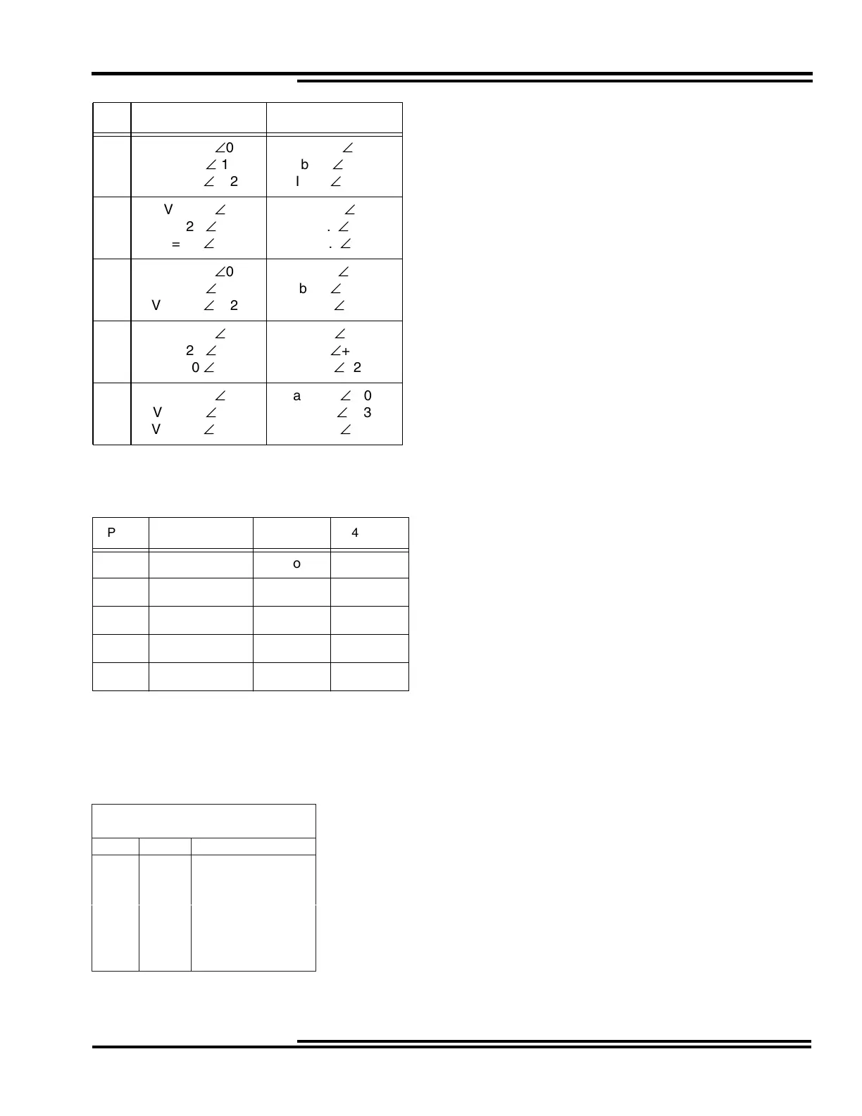
The apparent impedances seen by the relay in each of the above positions and the expected operation of the inner (21
BI) and outer (21 BO) blinders are the following:
Test #1 indicates the sequence of positions in the RX diagram to be applied and the time in cycles to hold the
position and the action of the relay.
The fault impedance measured should be 10.6 Ð 105 ohms.
V (Volts) I (Amps)
1
Va = 69
Ð
0
Vb = 69
Ð
-120
Vc = 69
Ð
+120
Ia = 5
Ð
-5
Ib = 5
Ð
-125
Ic = 5
Ð
+115
2
Va = 20
Ð
0
Vb = 20
Ð
-120
Vc = 20
Ð
+120
Ia = 4.5
Ð
-25
Ib = 4.5
Ð
-145
Ic = 4.5
Ð
+95
3
Va = 20
Ð
0
Vb = 20
Ð
-120
Vc = 20
Ð
+120
Ia = 6
Ð
-65
Ib = 6
Ð
+175
Ic = 6
Ð
+55
4
Va = 20
Ð
0
Vb = 20
Ð
-120
Vc = 20
Ð
+120
Ia = 4
Ð
-100
Ib = 4
Ð
+140
Ic = 4
Ð
+20
5
Va = 69
Ð
0
Vb = 69
Ð
-120
Vc = 69
Ð
+120
Ia = 6.5
Ð
-105
Ib = 6.5
Ð
+135
Ic = 6.5
Ð
+15
POS Z app 21 BI 41 BO
1 13.8 ∠5No No
2 4.47 ∠25 No Yes
3 3.33 ∠65 Yes Yes
4 5.00 ∠100 No Yes
5 10.6 ∠105 No No
TEST #1
Trip OST on the Way Out
Pos Time Trip Action
A
160
25
320
45
5 60 50-67 ms after 2

 Loading...


