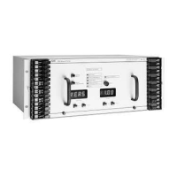
ABB REL 356 Current Differential Protection
3-11
Settings and Application
Case 3
When the minimum ground fault current is less than 12.5% of minimum three phase fault current C0 should be set to 2.5.
The recommended settings
C1 = 0.1
C2 = 0.7
C0 = 2.5
gives the following sensitivity for different faults:
Three phase faults
min3min3min
1.01
φφ
IICIT ⋅−=⋅−=
Phase-phase faults
min3min3minmin
60
min
33.0
2
3
38.038.0)21(
3
1
φφφφφφ
IIIIeCCIT
j
⋅=⋅⋅=⋅=⋅⋅+−=
±
ο
Single phase to ground faults
minminmin
0.1)021(
3
1
GG
IICCCIT
φφ
⋅=⋅++−=
Automatic Channel Delay Measurement (ALDT)
The relay logic continuously performs a communication channel delay measurement. To use this feature, set ALDT to
YES. If fixed channel delay, as set by LDT, is to be used, set ALDT to NO.
Lead/Follow Mode (LDFL)
The LDFL is used for automatic channel delay measurement. One terminal should always be set to LEAD and the other
to FOLO.
Local Delay Timer (LDT)
REL 356 uses the LDT setting when no automatic channel delay measurement is being used (ALDT = NO). If fixed
channel delay is used, LDT should be set to the channel delay displayed in MLDT function of the monitoring functions.
The LDT setting is used for loop-back testing, when automatic delay measurement cannot be performed. Then, set LDT
= 1.3 for digital versions and 19.3 for audiotone version. (NOTE: The 19.3 msec delay is valid for modem version A, i.e.
cat.# MCxxxxAxxx. For modem version T, LDT should be set to 10.8 msec.)
When ALDT = YES, the LDT setting is ignored by the system.
Unit Identification (UNID)
This setting eliminates the possibility of connecting two wrong units to each other due to cross connection in the
communication channel matrix.
The UNID numbers in the two units should be adjacent, i.e.
0 in one and 1 in the other
2 in one and 3 in the other
10 in one and 11 in the other
The lower value of the pair should always be an even number.
 Loading...

