ABB REL 356 Current Differential Protection
2-4
Installation, Operation and Maintenance
Display Module
The Display module interfaces with the Processor 1 system of the Microprocessor module. The Display module con-
tains:
• 2 blue-vacuum fluorescent alphanumeric displays or one LCD display for value and function fields (each field
has 4 characters)
• 7 LEDs (with 7 corresponding keys for selection purposes) provide function interpretation capabilities
The LEDs indicate:
• Relay In Service
• Settings
• V/I/Angle
• Last Fault
• Previous Fault
• Value Accepted
• Test
When the “Relay In Service” LED illuminates, the REL 356 relay is in service, there is dc power to the relay and the relay
has passed the self-check and self-test. The LED is turned OFF if the relay has at least one of the internal failures
shown in the TEST mode.
The “Value Accepted” LED flashes once to indicate that a value has been entered successfully.
The 7 push-button switches are used to activate the following functions on the front panel:
• Display Select (the LED’s, to the right of this push-button, indicate the selected function)
• Reset
• Function Raise (move to the following function)
• Function Lower (move to the previous function)
• Value Raise (move to the next higher value)
• Value Lower (move to the next lower value)
• Enter (recessed for security purposes)
Power Supply Module
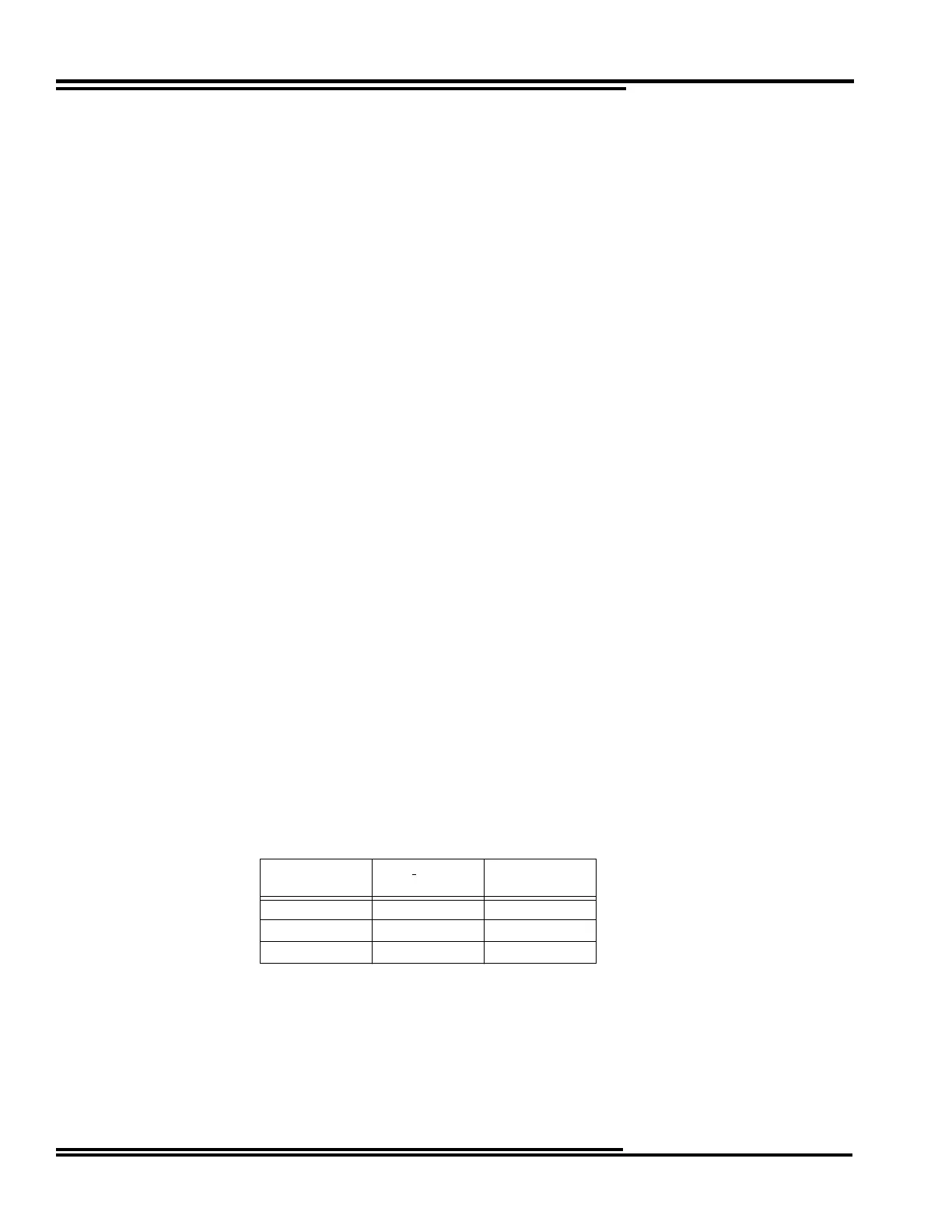
Three different styles of power supply boards are required to accommodate the input voltage ranges listed below. The
REL 356 relay is capable of continued operation during a 200 msec voltage dip from the dc battery input; the magnitude
of this voltage dip is also shown in the table:
Nominal
Battery (Vdc)
Input
Range (Vdc)
Voltage
Dip (Vdc)
48/60 38-70 28
110/125 88-145 73
220/250 176-280 146

 Loading...


