I.L. 40-386.3
4-24 (10/94)
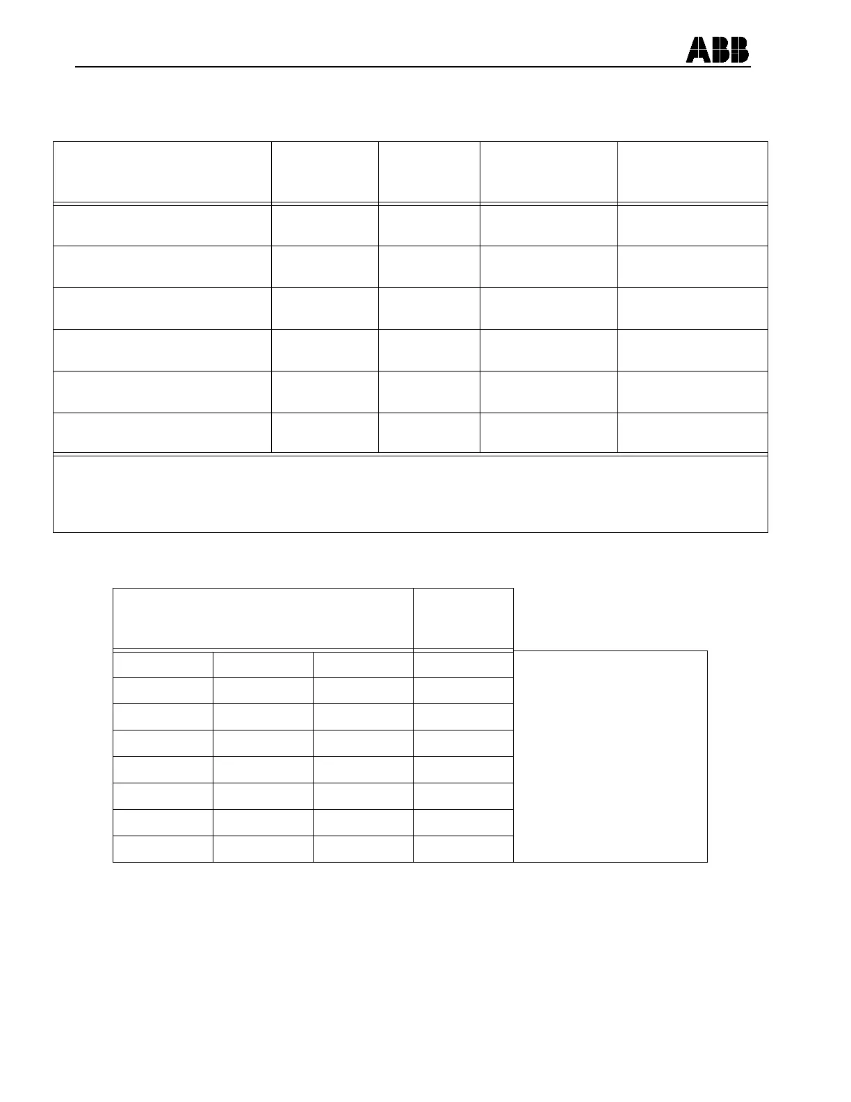
TABLE 4-5:
COMMUNICATIONS CABLE REQUIREMENTS
Connection Type Cable
(Straight = no
null modem)
Pins Req’d.
(All pins
not required)
Cable Connectors Notes
DB-25S, RS-232C connected to PC* Straight 2, 3, 7 To port: 25 pin DTE
To PC: 9 or 25 pin DCE
DB-25S, RS-232C connected to modem Null Modem 2, 3, 7 To port: 25 pin DTE
to Modem: 25 pin DTE
DB-9P, RS-232C connected to PC* Null Modem 2, 3, 5 To port: 9 pin DCE
To Modem: 25 pin DTE
See IL 40-610 For settings
DB-9P, RS-232C connected to modem Straight 2, 3, 5 To port: 9 pin DCE
To Modem: 25 pin DTE
See IL 40-610 For settings
DB-9S, RS-232C connected to PC* Straight 2, 3, 5, 7, 8 To port: 9 pin DTE
To PC: 9 or 25 pin DCE
See Table 4-6 For settings
DB-9S, RS-232C connected to modem Null Modem 2, 3, 5, 7, 8 To port: 9 pin DTE
To Modem: 25 pin DTE
See Table 4-6 For settings
* A communications cable kit (item identification number 1504B78G01) will accomadate most connection
combinations, in Table 4-5, is avaible through your local ABB representative.
Table 4-6:
DIP SWITCH SETTING CHART
Dip Switch Pole
123
Port Data
Rate (bps)
000300
Logic 1 is towards
Printed Circuit Board
Dip Switch poles 4 & 5
are not used
0 0 1 1200
0 1 0 2400
0 1 1 4800
1 0 0 9600
1 0 1 19200
1 1 0 1200
1 1 1 1200