I.L. 40-386.3
5-2 (10/94)
Acceptance Test
Before beginning any testing, verify that voltage selectable input, and contact config-
uration jumpers are in the correct position. The following tables, with appropriate ref-
erence figures, will provide a guide for the jumper settings. In-service settings may
vary according to specific applications.
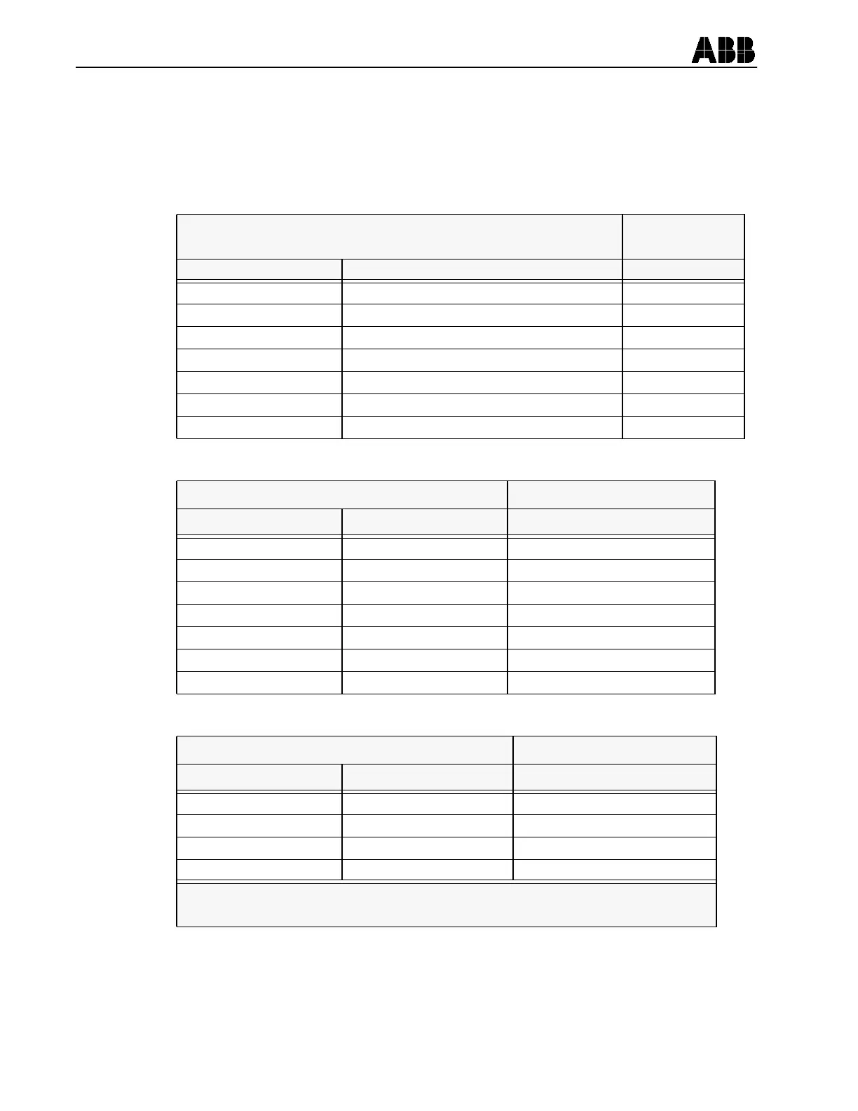
Filter Module
See Figure 5-1
for Location
Jumper Identification Jumper Purpose Factory Setting
P2 52 a Input Voltage Selection 48/125 Vdc
P18 52 b Input Voltage Selection 48/125 Vdc
P7 External Reset Input Voltage Selection 48/125 Vdc
P9 Pilot Enable Input Voltage Selection 48/125 Vdc
P10 Receiver 1 Input Voltage Selection 48/125 Vdc
P12 Sync-Check Voltage Reference VA
P13 Receiver 2 Input Voltage Selection 48/125 Vdc
Table 5-1:
Power Supply Module See Figure 5-2 for Location
Jumper Identification Jumper Purpose Factory Setting
JMP1 Carrier Stop Normally Open NO
JMP2 Carrier Send Normally Open NO
JMP5 Output contact 4 Normally Open NO
JMP4 Output Contact 3 Normally Open NO
JMP3 Output Contact 2 Normally Open NO
JMP6 Relay Fail Alarm AL1 Normally Closed NC
JMP7 Relay Trip Alarm AL2 Normally Open NO
Table 5-2:
Microprocessor Module * See Figure 5-3 for Location
Jumper Identification Jumper Purpose Factory Setting
JP3 Spare Jumper Storage IN (Jumper Present)
JP4 Trip Dropout Delay OUT (No Jumper)
JP5 Enable Output Test OUT (No Jumper)
JP6 A/D Calibration OUT (No Jumper)
* To verify or change jumper positions on the microprocessor module it is
necessary to remove the front panel of the REL 301/302.
Table 5-3: