I.L. 40-386.3
5-6 (10/94)
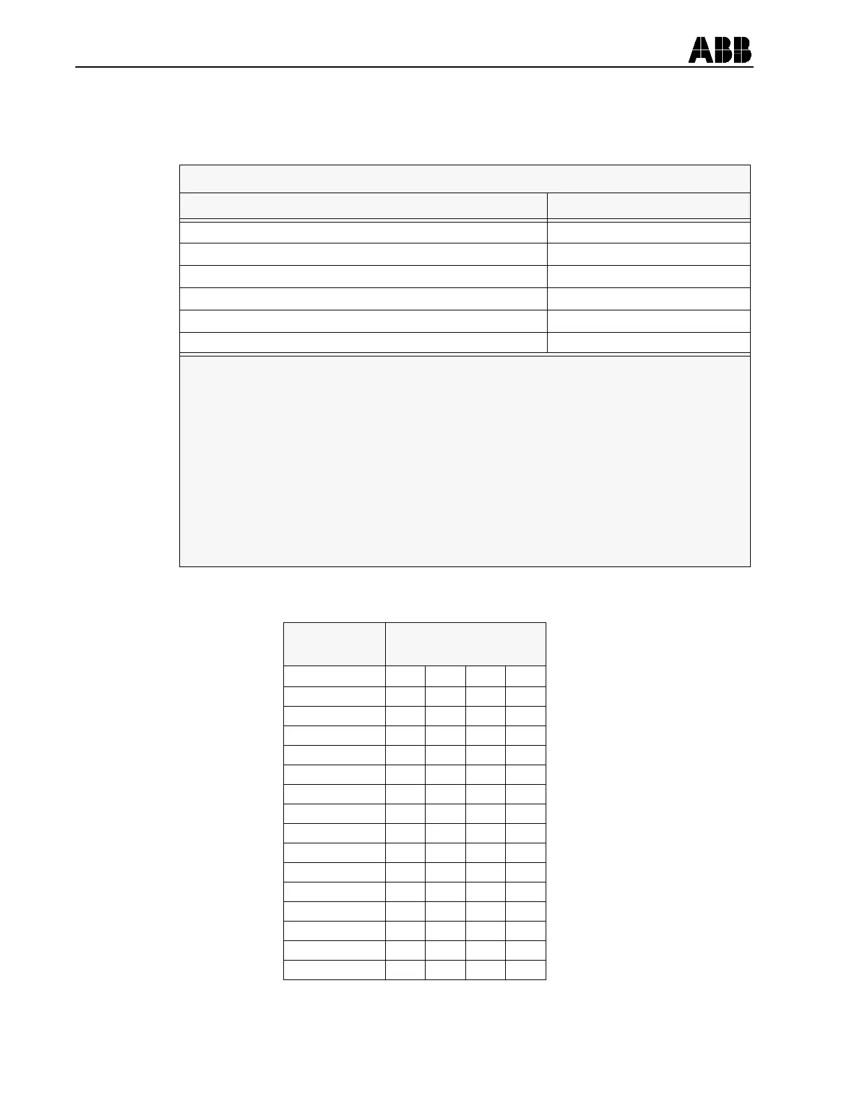
Using the following table, failure mode can be determined by equating bit numbers
(from above) to failure description. A bit set to “1” indicates the corresponding failure
has been detected.
For reference the binary-to-hexadecimal conversion is shown below:
RELAY STATUS FAILURE MODE
FAILURE DESCRIPTION BIT NUMBER
RAM Failure 0
EEPROM* Warning** 1
EPROM Checksum Fail *** 2
EEPROM Failure 3
Analog Input Failure 4
Microprocessor Failure 5
* Electrically Erasable Programmable Read Only Memory (non - volatile memory
** “EEPROM Warning” indicates a non-fatal error related to the failure of the
EEPROM check routine. All data stored in the EEPROM is written to 3
identical arrays.
These arrays are continuously checked for agreement with each other. If any
of the 3 arrays disagree (2 arrays must agree with each other) an “EEPROM
Warning” is given. This is the only failure which does not take the protection
out of service. (Also the “Protection In-Service” LED remains lighted.)
*** EPROM Checksum Failure indicates the program memory has failed.
With the exception noted above, (“EEPROM Warning”) relay tripping is blocked
to prevent false operation, upon failure of the self-check routine. Also the
“Protection In-Service” LED goes out.
HEX DIGIT
BINARY
REPRESENTATION
0 0000
1 0001
2 0010
3 0011
4 0100
5 0101
6 0110
7 0111
8 1000
9 1001
A 1010
B 1011
C 1101
D 1101
E 1110
F 1111