I.L. 40-386.3
5-12 (10/94)
NOTE: Testing of the trip contacts generates a target which is reported as sim-
ply “Test” in the display. Trip contact testing is the only contact test
which generates a target.
In the “TEST” mode verification of the LEDs functioning is accomplished by scrolling
to the “LEDs” “Protection” display and pressing the ENTER push-button. The protec-
tion LEDs will light in the following sequence and remain lit while the ENTER push-
button is depressed:
1. Pilot (REL 302 only) 6. BG
2. Zone1 7. CG
3. Zone2 8. MØ
4. Zone3 9. Other
5. AG
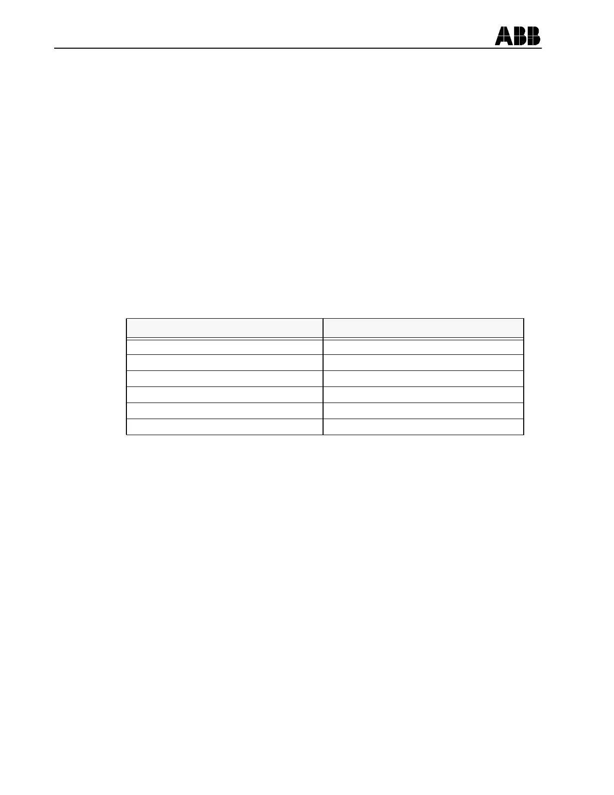
The following inputs can be tested, in the “TEST” mode, By applying voltage to each
input and observing the “Inputs” display. Scroll to the “Inputs” display, apply rated
voltage and as each input is energized, the associated display segment changes from
“–” to “|”.
This completes the REL 301 and REL 302 (non-pilot) Acceptance Test.
5. 2. PILOT ACCEPTANCE TESTS (FOR REL 302 ONLY)
5.2.1 Non-Pilot Acceptance Tests for REL 301/302
Perform the acceptance test procedures in Section 5.1 if not previously completed.
These tests are valid tests of hardware and firmware performance for either REL 301
or REL 302.
5.2.2 Input Opto-Coupler Check
STEP 12
Pilot Enable (PLT ENA)
In Step 3, Section 5.1, the settings from Table 5-2 should have been loaded for Non-
Pilot Acceptance Tests. Change the following settings using the procedure in Step 4
above:
“Pilot” = “YES” (Remote pilot control setting)
“SystType” = “Blocking” (Pilot system selection setting)
Input Under Test Display
52a |- - - - -
52b - | - - - -
EXT RESET - - | - - -
PLT ENA (Pilot Enable, REL 302 only) - - - | - -
RCVR1 (Receiver 1, REL 302 only) - - - - | -
RCVR2 (Receiver 2, REL 302 only) - - - - - |