I.L. 40-386.3
2-26 (10/94)
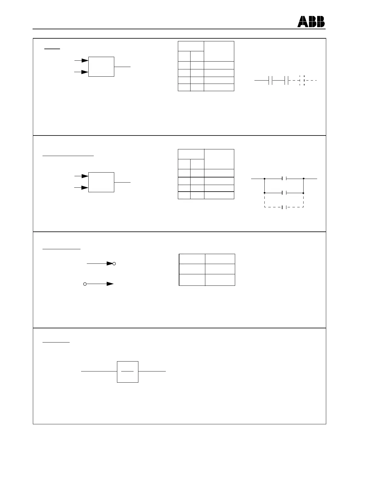
Figure 2-5a. Logic Drawing Symbols
AND
AND
INPUTS
A
B
OUTPUT
INPUTS
OUTPUT
AB
0
0
I
I
0
I
0
I
0
0
0
I
AB
ELECTROMECHANICAL
CONTACT EQUIVALENT
SIGNAL ON ALL INPUTS REQUIRED TO PROVIDE AN OUTPUT
Notes: I – Active state of a signal (may be defined as positive or negative voltage or current)
0 – Inactive state of a signal (reference)
– Can have more than two (2) inputs
OR
INPUTS
A
B
OUTPUT
INPUTS
OUTPUT
AB
0
0
I
I
0
I
0
I
0
I
I
I
ELECTROMECHANICAL
CONTACT EQUIVALENT
SIGNAL INPUT WILL PRODUCE AN OUTPUT
ALL INPUTS PRODUCE AN OUTPUT
A
B
✝
✝
✝
✝
✝
INCLUSIVE OR
INPUTS
OUTPUT
0
I
I
0
NEGATION (NOT)
INPUT
INPUT
OUTPUT
OUTPUT
OR
ABSENCE OF INPUT SIGNAL PRODUCES OUTPUT
TIMERS
INPUT OUTPUT
TP
TD
Input changes to Active State “1” -
Output changes to Active State After
Time Delay “On Pickup” (TP)
Input Changes to Inactive State “0”
(Only After Having Been Active) -
Output Changes to Inactive State After
Time Delay “On Dropout”