I.L. 40-386.3
(10/94) 4-7
• Relay Output Test
All relay outputs can be tested using the procedure described below
(1) Open the red FT switches, of the breaker trip circuits, making sure that the following FT
switch is not opened:
FT-5 BFI/Reclose Enable
(2) Move the spare blue jumper to position JP5 on the Microprocessor module.
(3) Press the SELECT push-button until the TEST mode is displayed; then depress the RAISE
or LOWER key until the output function to be tested appears in the FUNCTION and VALUE
fields, respectively.
(4) Press the ENTER push-button for the desired duration of the output relays operation.
(5) Press the RAISE push-button to select the following parameters, as desired:
NOTE: Pressing the ENTER push-button operates selected output relays.
(6) After completion of this test, restore the system to its operating state by moving the blue
jumper to position JP3 on the Microprocessor module, and closing the FT switch red
handles.
4. 5. JUMPER CONTROLS
All jumpers are set at the factory; the customer normally does not need to move the
jumpers. Refer to Tables 5-1, 5-2 and 5-3 for the recommended jumper positions.
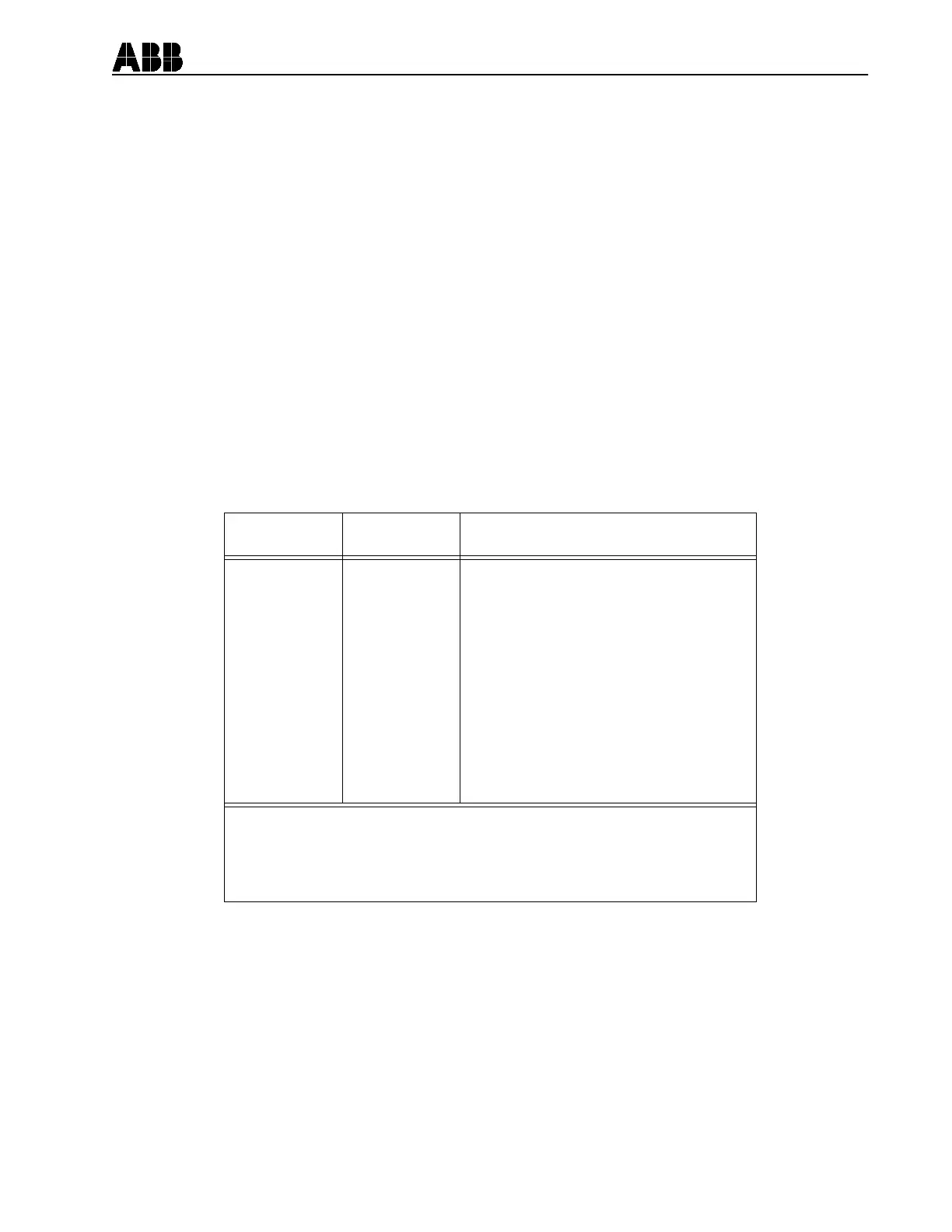
Function
Field
Value
Field Description
m RX1
m RX2
m RX1, RX2
Trip
BFI
RI2=3RI
RB
u Fail Alarm
Trip Alarm
Gen Start
m Send
m Stop
s OC1
s OC2
s OC3
s OC4
s OC5/Stop
Simulate
Simulate
Simulate
Relay
Relay
Relay
Relay
Relay
Relay
Relay
Relay
Relay
Relay
Relay
Relay
Relay
Relay
Carrier Receiver #1 Simulated Test
Carrier Receiver #2 Simulated Test
Carrier Receiver #1 and #2 Simulated Test
Trip
Breaker Failure
3-Pole Reclose Initiate
Reclose Block
Failure Alarm
Trip Alarm
General Alarm
Send
Stop
Programmable Contact Output, 1
Programmable Contact Output, 2
Programmable Contact Output, 3
Programmable Contact Output, 4
Programmable Contact Output, 5/Stop
Note: m denotes for pilot option only.
u a Vac balanced 3-phase voltage must be applied to relay
for change of state to occur; without it the Failure alarm is
always in the Alarm State.
s denotes available with programmable contact output option.