15
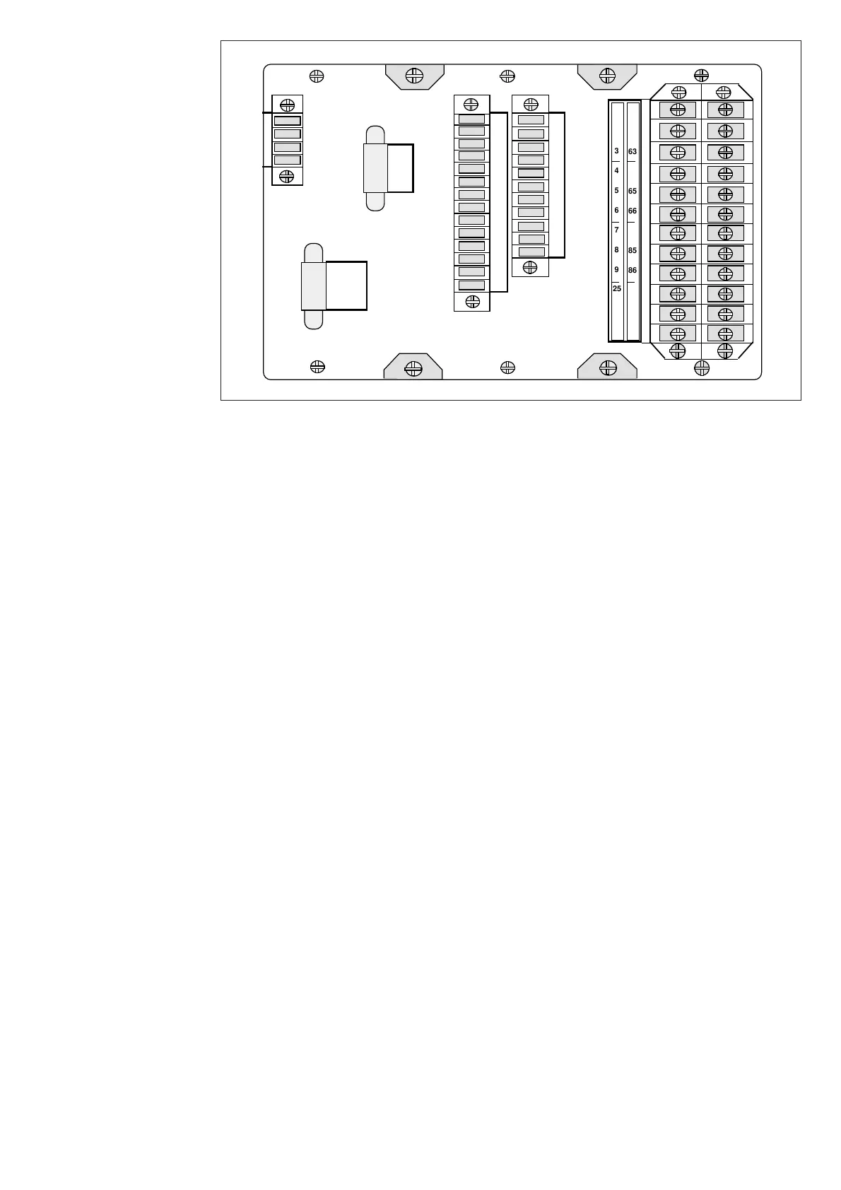
Fig. 7. Rear view of feeder terminal SPAC 310 C and SPAC 312 C
All external conductors are connected to the
terminal blocks on the rear panel. Terminal
block X0 consists of fixed screw terminals fas-
tened to the energizing input module. The
connectors X1…X3 are detachable multi-pole
connector strips with screw terminals.
The male part of the multi-pole connector strips
are fastened to the mother PC board. The fe-
male parts with accessories are delivered to-
gether with the feeder terminal. The position of
the female connector part can be secured by
means of fixing accessories and screws on the
end of the connector.
The measuring signal inputs, auxiliary voltage
supply and OPEN and CLOSE contact outputs
are connected to the terminal block X0. Each
terminal is dimensioned for one or two max. 2.5
mm
2
wires. The wires are fastened with M 3.5
Phillips cross slotted screws (recess type H). The
terminal block is protected by a transparent
shroud.
The signalling contact outputs are connected to
the multi-pole connector X1. The input chan-
nels 1…3 and 4…8 are connected via connector
X2. Input channel 9 is wired via connector X1
and the two mA inputs via connector X3. One
max. 1.5 mm2 wire or two max. 0.75 mm
2
wires
can be be connected to one screw terminal.
The rear panel of the feeder terminal is provided
with a serial interface for the SPA bus (RS 485).
Two types of bus connection modules are avail-
able. The bus connection module type SPA-
ZC 21 is fitted directly to the 9-pin D-type
subminiature connector. The bus connection
module SPA-ZC 17 includes a connection cable
with a D-type connector. Thus the connection
module can be installed at a suitable place in the
switchgear cubicle within the reach of the con-
nection cable.
The 9-pole D-type subminiature connector
INTERLOCK is reserved for future use.
1
2
3
4
5
6
7
8
9
25
26
27
61
62
63
65
66
85
86
Rx
Tx
X0
1
2
3
4
5
6
7
8
9
10
11
12
13
14
X2
1
2
3
4
X3
1
2
3
4
5
6
7
8
9
10
11
X1
INTER-
LOCK
Terminals
and wiring