Do you have a question about the ABB SPAC 310 C and is the answer not in the manual?
Describes the intended use of the feeder terminals for protection and remote control interface.
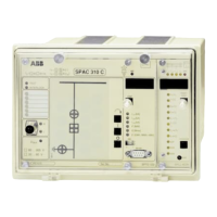
Details the modular structure and physical arrangement of the feeder terminal's components.
Explains the low-set and high-set overcurrent stages and their characteristics.
Details the two-stage earth-fault protection based on neutral current measurement.
Covers status indication of objects and local/remote control capabilities.
Describes the user-programmable feeder-based interlocking system.
Explains direct control of outputs based on programmed logic and input status.
Details measurement of phase currents, active/reactive power, and energy.
Covers front and rear panel serial ports for programming and bus connection.
Illustrates wiring and module interconnections for SPAC 310 C.
Describes rear panel connections, terminal blocks, and communication ports.
Covers voltage checks, auxiliary supply, and programming steps.
Details parameters that can be programmed via RS 232 or RS 485.
Explains factory default settings and how to change them.
Specifies input capabilities, ranges, and current drains for various inputs.
Defines low-set and high-set stages for overcurrent and earth-fault protection.
Covers control, measurement, and data communication functions.
Specifies environmental operating conditions and electrical test requirements.
Reads binary input signals, indicates status, and performs OPEN/CLOSE commands.
Measures currents, power via mA signals, and uses input 7 for energy pulses.
Details object status indicators, input channel indicators, and key switch.
Explains the RS 232 interface for programming and configuration.
Explains object configuration, default settings, and commands.
Explains the purpose and programming of interlocking via SPA bus.
Controls outputs based on programmed logic and input status.
Lists output codes for OPEN, CLOSE, SIGNAL 1-3 and their control methods.
Explains scaling for phase currents, active/reactive power.
Details using input 7 as pulse counter or integrating measured power.
Explains event representation, masks, and calculation for reporting.
Lists data available via SPA bus and parameters for transfer.
Lists default values for parameters after factory testing.
Details configuration, inputs, outputs, and interlocking for default 1.
Details configuration, inputs, outputs, and interlocking for default 2.
Details configuration and interlocking for default 10, with reversed colours.
Lists overcurrent/earth-fault stages and inverse time characteristics.
Details single/two/three-phase overcurrent protection, stages, and characteristics.
Describes single-pole earth-fault protection, stages, and characteristics.
Shows the block diagram for the combined overcurrent and earth-fault relay module.
Explains start/operation indicators, TRIP indicator, and phase fault indication.
Details setting values for I>, t>, k, I>>, t>>, I0>, t0>, k0, I0>> stages.
Selects overcurrent/earth-fault characteristics and CBFP.
Routes blocking signals, selects settings, and configures latching.
Selects start/operate signals to outputs SS1, SS2, SS3, and TS1/TS2.
Details recorded data like phase currents, start durations, and number of starts.
Explains inverse time characteristics and their parameters.
Details RI and RXIDG characteristics for protection.
Specifies start current, operate time, characteristics, and accuracy.
Explains event codes, masks, checksums, and SPA bus data transfer.
Lists fault codes, their types of errors, and their meaning.
| Display Size | 10.4 inches |
|---|---|
| Display Type | TFT LCD |
| Resolution | 800 x 600 pixels |
| Touch Technology | Resistive |
| Connectivity | Ethernet, Serial |
| Ethernet | 10/100 Mbps |
| Serial Ports | 2 x RS-232/485 |
| Ingress Protection | IP65 (front) |
| Weight | 2.5 kg |